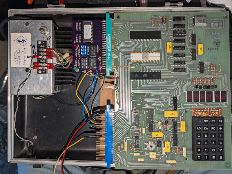
At the very start of the personal computer revolution, there were relatively inexpensive boards with little more than a CPU, some memory, a display, and switches or a keypad. Some of these had expansion ports meant to allow you to build up, and some were just “trainers” to learn about computers. While you could argue that the Altair fell into this category, it had a case and a proper bus. The computers we are thinking about were usually just on a single board and — with luck — had an edge connector for expansion. Perhaps the most famous of these was the KIM-1 and [Old VCR] shows us how he brought one back to life.
These were highly popular mainly because of the low price of $245 back in 1976. For that price you got a calculator-style keyboard and LED display, 1K of RAM, and 2K of ROM. [Old VCR] has several and noticed that one was developing memory problems.
Some basic troubleshooting found the culprit to be the memory chip at U10 on the schematic. Piggybacking a good RAM chip proved the chip was at fault, and, of course, there was no socket, so surgery ensued!
On the old boards, it is hard to remove a part without damaging traces and this was no exception. Silver conductive ink fixed the trace, but the repair was unsuccessful. That’s when the diagnostic board — a design from [Dwight Elvey] makes an appearance.
Spoiler alert: the culprit was a solder bridge, also easy to do on these old boards. Removing the short put the old computer back in tip-top shape.
If you want your own KIM-1, you can do a modern build one pretty easily and save most of the $5,000 or so that a real one would cost. Or grab an Arduino. If you do the latter, you can also make it into a passable COSMAC Elf.


“… and save most of the $5,000 or so that a real one would cost.”
Really? I have one sitting in a drawer, complete with manuals and all sorts of stuff. Good job I never gave it away as I intended to! I wonder if it still works………
Yeah, I’ve got two in my file drawer, but only one full set of manuals and the little cheat card. Mine are rev 1 (got them both in ’76), with the ceramic packages for all three of the 40-pin DIPs. I got one out a couple years back and it still worked, so cool…
” Mine are rev 1 (got them both in ’76)” I am going to have to fish it out and take a look – I honestly can’t remember if it is Rev1 or not, I don’t remember ceramic packaging so maybe not. It actually came from someone else who was moving on to something bigger; RM380Z I think, but it was a lonng time ago, so…. If it was a 380Z it would fit in around ’77 to ’85ish.
To be honest, the solder bridge could only happen because [Old VCR] just had used way too much solder on that pin. You don’t need that much solder. The PCB is 1mm thick (maybe even 1.5mm). So if you fill the hole with solder, the pin already connects to the pad via 1mm of solder. No need to put another 1mm-high blob on top of that and make it 2mm. There’s too few solder, but there’s also too much solder. Solder should be a nice cone on the pin, and nothing more.
https://learn.adafruit.com/adafruit-guide-excellent-soldering/common-problems
Well, clearly, you should never have opens or shorts or any of that. But boards without solder mask and close traces, it is an easy error to make. If you’ve only worked on modern boards, it is hard to realize how easy it is to delaminate, bridge, and otherwise hose up the older boards.
A nice cone or volcano shape. How often I see factory touch-ups where the wave process was less than perfect (dirty board) and with the telltale spheres of shine against dull soldering of cones? Lots! Flux! Not more solder.
I used to say like Epcot Center in Florida but now there is a bigger one in Vegas with lots of LED’s.
I used to have one of these. Picked it up at a hamfest in 1980 for $50
I once ran across a solder bridge issue when repairing an Apple II way back when, but not this kind. The board had been placed on a bench top where other repairs were done, and a small ball of solder wedged itself between two of the pins on an IC socket on the underside of the board. Took a lot of time to figure out that one!
I had a SYM-1 which was very similar. I remember connecting a TMS9918A based video board to it and writing a game called “Rat and Dragon” in assembler. I learned so much from this my first computer.
I have a MEK6800D2 kit up in the attic. Not as compact as the KIM-1 but you could expand it by adding RS232 chips and changing out the ROM for a serial monitor. I think you could even put it into a chassis with a backplane, but I never got that far.
Yea, me too! I made it play tunes by connecting a speaker to one of the I/O lines and toggling it at different speeds.
Motorola 6800 CPU running at about 700kHz clock speed IIRC, with ¼ KB (256 bytes) of user RAM, and another 128 bytes for the “monitor” (built in ROM which drives the keyboard and 7-sement displays) to use.
“On the old boards, it is hard to remove a part without damaging traces …”
It is not hard, it just requires some practice. Cut out the IC body, remove pins one by one and clean up with solder braid. Those old thru-hole boards with their fat traces can take a lot of abuse, they were designed for wave soldering and occasional repairs during the manufacturing process.
Those boards didn’t even have solder mask, so I doubt it was intended for wave soldering.
You don’t need a solder mask for wave soldering if you stick to certain design guidelines, you can even mount SMD parts on the solder side.
Sure, if the spacing’s wide enough, which that board definitely doesn’t look like it has. Although after looking at it, the *backside* does have mask.
I’ll say they were cheap. I got mine for free.in 1979. A friend went to a seminar about microprocessors paid for by the company. It included a “free” KIM-1. Someone else attennding didn’t want his, so.I got it. My first computer.
You could cut the legs off those thru hole chips. Then remove the pins one at a time or just solder the new one onto the old legs.
Sure, you can cut the legs off the chips and remove the remnants more easily and with less chance of damage but you’d really want to be certain the chip was faulty before you destroyed it because some of them have significant value now and collectors like their old hardware to have contemporary parts, replacing a ’75 date code chip with a ’90 chip might detrimentally affect the value for some.
The best advice is to learn to solder and re-work boards properly or give it to someone who has those skills.
Fascinating little machine!
Though like the Cosmac VIP, it’s not exactly a “computer”.
It’s too limited to do word processing, even.
There’s even an ancient KIM emulator running on C64. So simple it is.
It’s more like a oversized microcontroller or a “teaching computer” (primitive programmable caculator).
Something that was available as an option for electronic construction kits.
Like the Busch/Elotronic Microtronic-Computersystem 2090 (aka Busch Education Computer 2090).
Or Sharp MZ-40K..
You keep saying that,but you weren’t there. In 1975, people wanted a home computer, they weren’t thinking of what they’d do with it. Many didn’t a software background, they knew the hardware.
It was only with time, and cheaper hardware, that people refocused on using them.
And the Altair came with 256 bytes of memory, andno interface other than the front panel. Not as useful as the KIM-1. You could expand it, but you could expand the KIM-1.
It’s”let’s have computers” led to their place in society.