[OZ2CPU] has an HP power supply that is about 30 years old. It looks brand new, though, and has three outputs and includes tracking for the adjustable positive and negative supply. After a quick demo of the unit’s features, he tears it all down so we can see inside. You can catch the video below.
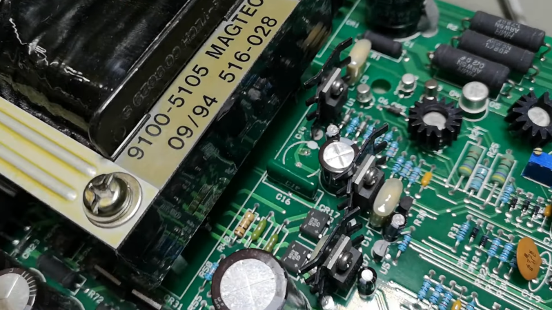
Some similar supplies offer a 10-turn adjustment knob, but this one doesn’t. Inside is a beefy transformer and quite a few through-hole components. There was room to change the main adjusted pot to a 10-turn unit, so he made the mod.
Testing was mostly good, but there was some oscillation in certain situations. To tackle that, he worked through it with another unit in the second video below. The new unit had the same behavior. He probed around and found that one capacitor leaked electrolyte, which didn’t fix the problem.
Analyzing the schematic was more productive. A feedback transistor had excessive gain at high frequency. This appears to be a design problem, and adding a resistor into the feedback loop makes it work as expected.
It is hard to go wrong with a name-brand power supply, but, as this shows, they are not always perfect. You can, of course, roll your own. You can make them very fancy if you like.


I would like to mention Gerry Sweeney’s blog for repairing an HP E3634A power supply.
https://gerrysweeney.com/hpagilent-e3634a-power-supply-teardown-repair/
At school in 1970 I tested an HP power supply and noticed that it had a negative output impedance. My teacher said that if a capacitor of the right value were connected to the output, the supply would oscillate (a surprise to me). Apparently this design flaw in HP supplies has been around for a long time.
…..and often you can trace pervasive design flaws like this to a particular indicvidual’s direct or indirect influence. I made a lucrative living from untangling similar and showing various Silicon Valley companies that they could in fact break away from the way they had always done it.
“Some similar supplies offer a 10-turn adjustment knob, but this one doesn’t. Inside is a beefy transformer and quite a few through-hole components.”
a) “beefy” isn’t wrong, but the transformer isn’t that huge, either.
Those big ones in 13,8v lab PSUs used to be normal sized
b) “through-hole components”.
The term is correct, but Jesus.. 🙄 They’re just normal components.
Surface-mounted components are the weirdos.
The explanation is simple: They heat up during soldering.
With “through-hole components”, by contrast, the heat coming from the soldering iron is being transfered to the PCB’s copper layer or the pliers.
It won’t reach the component. Or not fully.
That’s just one of the reason why through-hole components are superior.
Second is mechanical stability.
They won’t fall off due to temperature or vibration.
Third one is grounding/shielding. Eith through-hole, it’s possible to have a grounding layer between the upper and lower PCB side. With SMD, component and pins are on same side, there’s no insulation anymore.
Unfortunately, there’s little to no insight these days.
The upcoming generation grows up with SMD.
It’s hard to it to realize that SMD was intended for machines (robotic assembly).
That paradigm started with the colored resistor rings. Early resistors had values written to them in human readable form.
..
Otherwise, the article is fine, I think.
It’s refreshing to see a proper power supply once in a while, too. 🙂👍
Thought-hole components are much bigger, reducing the possible density of a board. Also, the holes through the board go through all layers, reducing the space available for traces. Would you like a phone or laptop build with through-hole components?
Through-hole components cause much bigger loop area, since they are bigger and further from the ground plane, which in turn causes much greater parasitic inductance.
SMD components are much less susceptible to vibrations, since they don’t form a mass-spring system with a particular resonant frequency, like through-hole components do. Also, the ratio of mass to mechanical strength of the joint is much better for small SMD components. Notable exceptions are electrolytic capacitors (which are always big and heavy) and connectors, where the stronger through-hole connection is beneficial to deal with the forces applied by cables being pulled.
To be brutally honest, I think you’re the one missing insight. If through-hole really was superior, we’d see new devices designed with that where reliability is more important than cost.
Actually THT parts have mechanical resonance around 4-6 GHz, not an issue unless youre making jest engines or guided 155 shells. And even then it can be damped with liberal application of sanitary silicone.
“That paradigm started with the colored resistor rings. Early resistors had values written to them in human readable form. ”
Are you saying the resistor color code was invented for robotic assembly? And that early resistors used actual numbers printed on?
The only early resistors I have seen with numbers printed on were those really big ceramic ones. People used to pull those out of broken equipment and used them as knife sharpening stones. That’s how I first saw them. And as far as I know really big ones still do print the numbers on. Certainly the ones in TO220 cases still do.
The color code has been around for a very long time though. It’s been around longer than “colored resistor rings”. Have you never seen a dogbone resistor? https://youtu.be/ofgxKFn4Am8
I don’t think those were designed for robotic assembly. Unless maybe they were going to give this guy a job https://youtu.be/AuyTRbj8QSA
Surely at least part of the rationale behind resistor colour coding was that the parts were getting smaller, especially with the advent of solid-state components. It’s easier to read colour bands than numbers when the parts get small. Plus, I’ve worked on LOTS of tube equipment from a time when semiconductors were relatively new, and automated assembly was not that common. Yet almost without exception they were colour coded, so I’m not sure your claim is valid. One exception is power resistors – they can heat up enough to alter the colours, and I think that’s why numbers are used on them.
As for through-hole vs surface mount, anyone who has worked on RF design in or near UHF realizes that SMT is a godsend. At those frequencies, shorter lead lengths and fewer changes in conductor shape and dimensions are really worthwhile. Yes, it’s certainly workable to use through-hole components at those frequencies, and I did a lot of that work. But SMT brought a lot to the table when it came to reducing parasitic capacitance and, especially, inductance.
The open loop bandwidth issue may be a problem with early JEDIC Standards. The 2N3054,5 families did not specify Safe Operating Area. The 2N3055 had a 60 Vceo and 115 Watt. HFE GBw 800 KHz min. The DC Safe Operating was almost complete to basic ratings. But later same number was applied to a 4MHz GBw version. Sam’s 60Vce and 15A Ice. But SOA only 20msec at rated Vce Ice. They both had the same JEDIC designation but different fab techniques. Maybe your power supply had the faster part.
I started electronics back on the late 1950s and low power resistors have always had color code strips
wow I am honored, two of my videos featured on hackaday :-)
I am that dude OZ2CPU from that youtube channel: oz2cpu teardown
you will be able to find quite a few other units tested, repaired, and funny design ideas explained :-)
just did a count : 657 videos to be exact..