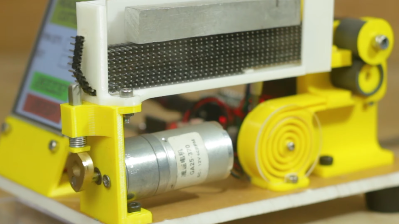
In most cases, cutting pin headers is a pretty simple job to tackle with a pair of cutters or even your bare fingers. But if you’re doing a lot of it, like for kitting up lots of projects for customers, then you might want to look at something like this automatic pin header cutter.
Even if you don’t need to follow [Mr. Innovative]’s lead on this, it’s worth taking a look at the video below, which has a couple of cool ideas that are probably applicable to other automation projects, especially those where lots of small parts are handled. Processing begins with a hopper that holds a stack of header strips over what we’d call a “reverse guillotine,” consisting of a spring-loaded plunger riding on a cam. A header strip is pushed out of the hopper to expose the specified number of terminals, the cam rotates and raises the plunger, and the correct length header is snapped off.
For our money, the neatest part of this build is the feed mechanism for the hopper. Rather than anything complicated like a rack-and-pinion, [Mr. Innovative] opted for a pusher made from a stiff yet flexible strip of plastic, which is forced along the bottom of the hopper by a pair of stepper-driven drive rollers. The plastic pusher is stored rolled up in a spiral fixture so it doesn’t take up much room.
Overall, it’s a simple and largely effective design. [Mr. Innovative] does express a little dissatisfaction with some aspects of the build, though; it looks like the stack of header strips needs a little weight on top of it to keep them feeding properly, and we notice a couple of iterations of the cutting mechanism in the video. The cut headers do seem to either fly off into the stratosphere or stay attached to each other, which could lead to jamming problems.
But still, it’s a solid design and reminds us of some other projects by [Mr. Innovative], like this SMD tape slicer or a CNC gear cutter.


He really needs an encoder or a pushed-at-one-point-in-the-cycle roller “limit” switch. otherwise the DC motor which is turning the cam will get out of sync at some point, one cannot rely on assumptions that amotor always turns the same distance in a given time when voltage is applied.
Having the cut piece fly off into the ozone is a problem when manually cutting also.
Meh, it’s easy to put something over it so the parts can’t fly away.
I have manually inserted hundreds of thousands of 3 pin headers for jumpers.
I used to have a simple and effective mass snapping jig, but eventually I found it best/fastest to pre-populate the jumpers onto the 40 way strips, then snap them off the strip with fine pliers, and insert directly to the pcb.
Now what would help, is a machine to put the jumpers onto the 40 way strips.
(Actually, this takes zero time, as I usually do it while I’m giving my 90 yo mother a damn good listening to on Prof Bell’s apparatus.)
Did anyone else notice that it doesnt actually work? Aside from the mashed up headers flying all over the room, he commands it to make 20x 5-pin segments and ends up with a bunch of 3, 4, and 5 long strips…
I agree, I was left heavily disappointed after watching the first 30s of the video and didn’t bother to continue watching the rest seeing how poor the results are for such an overcomplicated design.
Header pin distance challenge could be a GeekOlympic event!