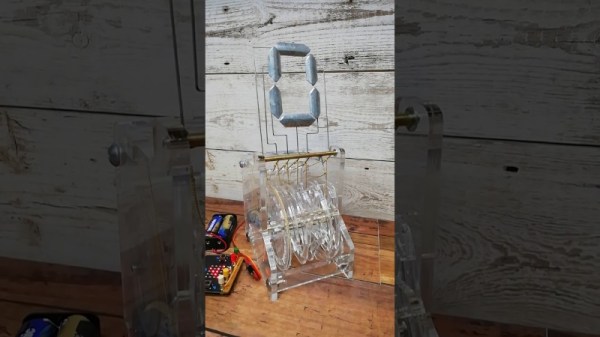
You never know when inspiration is going to strike, and for [Ekaggrat Singh Kalsi], it struck while he was playing with one of his daughter’s hair ties. The result is a clock called “Bezicron” and it’s a fascinating study in mechanical ingenuity.
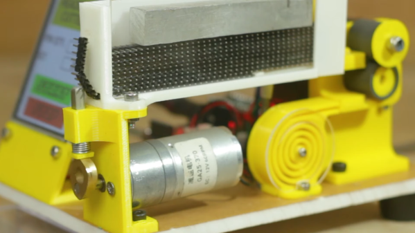
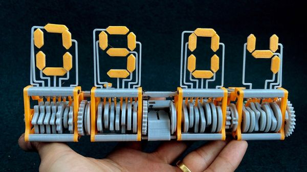
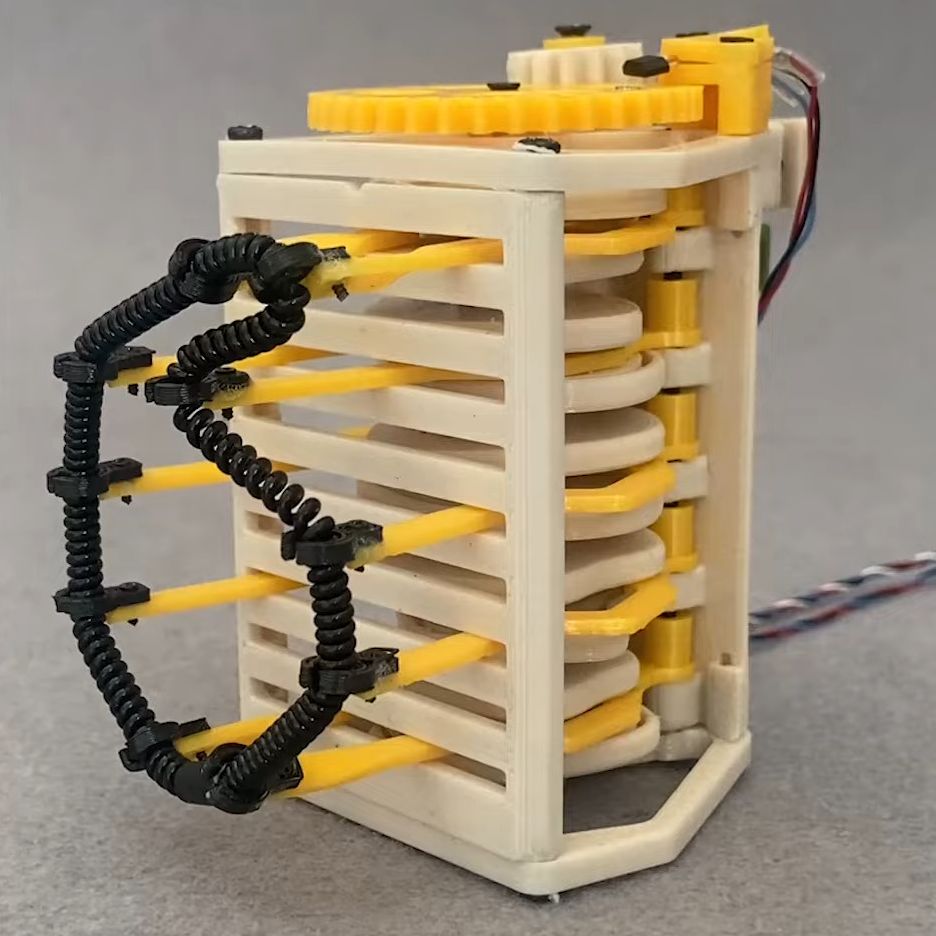 The hair ties in question are simple objects, just a loose polymer coil spring formed into a loop that can be wrapped around ponytails and the like. In Bezicron, though, each digit is formed by one of these loops fixed to the ends of five pairs of arms. Each pair moves horizontally thanks to a cam rotating between them, changing the spacing between them and moving the hair tie. This forms each loop into an approximation of each numeral, some a little more ragged than others but all quite readable. The cams move thanks to a geared stepper motor on the rightmost digit of the hours and minutes section of the clock, with a gear train carrying over to the left digit. In between is the colon, also made from springy things pulsing back and forth to indicate seconds. The video below shows the clock going through its serpentine motions.
For our money, the best part of this build is the cams. Coming up with the proper shape for those had to be incredibly tedious, although we suspect 3D printing and rapid iterative design were a big help here. Practice with cam design from his earlier Eptaora clock probably helped too.
Continue reading “Springs And Things Make For A Unique Timepiece”