Hackaday Prize 2023: Over-the-Top Programmable Resistor Looks The Part And Performs

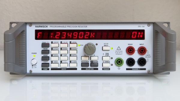
Every once in a while we get wind of a project that we’re reluctant to write up for the simple reason that it looks too good to be true. Not that projects need to be messy to be authentic, mind you, but there are some that are just so finished and professional looking that it gives us a bit of pause. [Sebastian]’s programmable precision resistor is a shining example of such a project

While [Sebastian] describes this as “a glorified decade resistance box,” and technically that’s exactly right — at its heart it’s just a bunch of precision resistors being switched into networks to achieve a specific overall resistance — there’s a lot more going on here than just that. The project write-up, which has been rolling out slowly over the last month or so, has a lot of detail on different topologies that could have been used — [Sebastian] settled on a switched series network that only requires six relays per decade while also minimizing the contribution of relay contact resistance to the network. Speaking of which, there’s a detailed discussion on that subject, plus temperature compensation, power ratings, and how the various decades are linked together.

For as much that’s interesting about what’s under the hood, we’d be remiss to not spend a little time praising the exterior of this instrument. [Sebastian] appears to have spared no expense to make this look like a commercial product, from the rack-mount enclosure to the HP-esque front panel. The UI is all discrete pushbuttons and knobs with a long string of 16-segment LEDs — no fancy touch-screens here. The panel layout isn’t overly busy, and looks like it would be easy to use with some practice. We’d love to hear how the front and rear panel overlays were designed, too; maybe in a future project update.

This honestly looks like an instrument that you’d pay a princely sum to Keithley or H-P to own, at least back in the late 1990s or so. Kudos to [Sebastian] for the attention to detail here.

Programmable Resistance Box

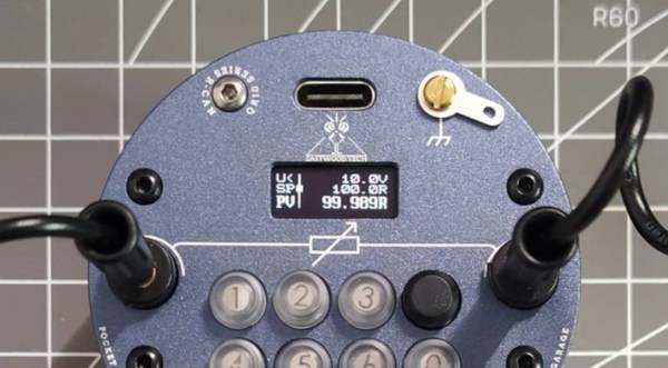
For prototype electronics projects, most of us have a pile of resistors of various values stored somewhere on our tool bench. There are different methods of organizing them for easy access and identification, but for true efficiency a resistance substitution box can be used on the breadboard to quickly change resistance values at a single point in a circuit. Until now it seemed this would be the pinnacle of quickly selecting differently-sized resistors, but thanks to this programmable resistor bank there’s an even better option available now.

Unlike a traditional substitution box or decade box, which uses switches or dials to select different valued resistors across a set of terminals, this one is programmable and uses a series of sealed relays instead. That’s not where the features stop, though. It also comes equipped with internal calibration circuitry which take into account the resistance of the relay contacts and internal wiring to provide a very precise resistance value across its terminals. It’s also able to be calibrated manually to account for temperature or other factors.

For an often-overlooked piece of test equipment, this one surely fits the bill of something we didn’t know we needed until now. Even though digital resistor substitution boxes are things we have featured in the past, the connectivity and calibration capabilities of this one make it intriguing.

An HP15-C emulator PCB

Calculate Like It’s 1989 With This HP15C Emulator

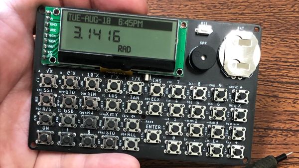
Back in the day, your choice of calculator said a lot about your chops, and nothing made a stronger statement than the legendary Hewlett-Packard Voyager series of programmable calculators. From the landscape layout to the cryptic keycaps to the Reverse Polish Notation, everything about these calculators spoke to a seriousness of purpose.

Sadly, these calculators are hard to come by at any price these days. So if you covet their unique look and feel, your best bet might be to do like [alxgarza] and build your own Voyager-series emulator. This particular build emulates the HP15C and runs on an ATMega328. Purists may object to the 192×64 LCD matrix display rather than the ten-digit seven-segment display of the original, but we don’t mind the update at all. The PCB that the emulator is built on is just about the right size, and the keyboard is built up from discrete switches that are as satisfyingly clicky as the originals. We also appreciate the use of nothing but through-hole components — it seems suitably retro. The video below shows that the calculator is perfectly usable without a case; a 3D-printed case is available, though, as is an overlay that replicates the keypad of the original.

We’ve seen emulators for other classic calculators of yore, including Sinclair, Texas Instruments, and even other HP lines. But this one has a really nice design that gets us going.

Continue reading “Calculate Like It’s 1989 With This HP15C Emulator”

Psion Organiser with a Pico memory pack.

Proto-PDA Regains Its Memory With The Help Of A Raspberry Pi Pico

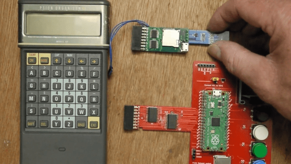
Remember the Psion Organiser? If you do, chances are you were an early adopter, as the 8-bit pocket computer had its heyday in the mid-1980s. Things have come a long way since then, of course, but just how far is illustrated nicely by the fact that a Raspberry Pi Pico can stand in for the Psion’s original memory packs.

Like many of the early attempts at putting a computer in your pocket, the Psion II had removable modules, which were dubbed “Datapaks”. The earliest versions of the Datapaks were little more than an EPROM chip on a small PCB, and the technical limitations of the day plus the quirky way of addressing the memory made it possible for [Amen] to mimic a Datapak using a modern microcontroller.

The first version was a breakout board that extended out of the Datapak slot significantly, with a Pico, OLED display, SD card slot, and a bunch of pushbuttons. That prototype proved that the Pico was indeed fast enough to fool the Psion into thinking a legit Datapak was plugged in. [Amen] later refined the design by making a board that stuffs everything into the Datapak slot, with the exception of the OLED which still dangles out where it can be seen. He puts the faux memory to the test in the video below.

It’s great to see groundbreaking tech of yesteryear like the Psion being taken care of and returned to use. We’ve seen others try before; here’s a hack that uses a Pi to connect a Psion Organiser to the internet through its RS-232 serial port.

Continue reading “Proto-PDA Regains Its Memory With The Help Of A Raspberry Pi Pico”

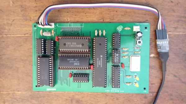
Build A Barebones 68000

The 68000 chip was ubiquitous in the computing world well past its heyday in the 1980s. It was used as the basis for many PCs and video game consoles, and even in embedded microcontrollers. Now, one of its niche applications is learning about the internal functions of computers. 68000 builds are fairly common when building homebrew computers from scratch, but projects like these can be complicated and quickly get out of hand. This 68000 project, on the other hand, gets the job done with the absolute minimum of parts and really dives into the assembly language programming on these chips. (Google Translate from Spanish)

[osbox68] built this computer by first simulating its operation. Once he was satisfied with that, the next step was to actually build the device. Along with the MC68008 it only uses two other TTL chips, a respectable 32 kilobytes of ram, and additionally supports a serial port and an expansion bus. A few 74-series chips round out the build including a 74HC574 used for debugging support. With a custom PCB to tie everything together, it’s one of the most minimal 68000 builds we’ve seen that still includes everything needed to be completely functional.

After all, including the TTL and 74XX chips the entire circuit board only uses 10 integrated circuits and a few other passive elements for a completely functional retro computer. [osbox68] also includes complete schematics for building a PCB based on these chips to make construction that much easier. Of course, emulating an old microcontroller instead of using TTL components can save a lot of real estate on a PCB especially if you’re using something like an FPGA.

Soviet Scientific Calculator Gives Up Its Cold War-Era Secrets

Say what you want about Soviet technology, but you’ve got to admit there was a certain style to Cold War-era electronics. Things were perhaps not as streamlined and sleek as their Western equivalents, but then again, just look at the Nixie tube craze to see where collectors and enthusiasts stand on that comparison.

One particularly interesting artifact from the later part of that era was the lovely Elektronika MK-52 “microcalculator”. [Paul Hoets] has done a careful but thorough teardown of a fine example of this late-80s machine. The programmable calculator was obviously geared toward scientific and engineering users, but [Paul] relates how later versions of it were also used by the financial community to root out banking fraud and even had built-in cryptographic functions, which made encrypting text easy.

[Paul] has put together a video of the teardown, detailing the mostly through-hole construction and the interesting use of a daughter-board, which appears to hold the high-voltage section needed to drive the 11-character VFD tube. The calculator appears to be very well cared for, and once reassembled looks like it would be up for another ride on a Soyuz, where once it served as a backup for landing calculations.

We love the look of this machine and appreciate [Paul]’s teardown and analysis. But you say that the Cyrillic keyboard has you stumped and you need a bilingual version of the MK-52? That’s not a problem.

3D-Printed Macro Pad Ditches The PCB With Slick Wiring Guides

Reddit user [duzitbetter] showed off their design for a 3D-printed programmable macro keyboard that offers a different take on what can be thought of as a sort of 3D-printed PCB. The design is called the Bloko 9 and uses the Raspberry Pi PICO and some Cherry MX-style switches, which are popular in DIY keyboards.

The enclosure and keycaps are all 3D printed, and what’s interesting is the way that the enclosure both holds the components in place as well as providing a kind of wire guide for all the electrical connections. The result is such that bare copper wire can be routed and soldered between leads in a layout that closely resembles the way a PCB would be routed. The pictures say it all, so take a look.

Bloko 9 is available as a paid model, and while going PCB-free thanks to 3D printing is a technique others have played with, it is very well demonstrated here and shows there is still plenty of room to innovate on the concept. DIY keyboard and macro pad design is also fertile ground for hackers; we have even seen that it’s possible to 3D print one right down to the switches themselves.