The common wisdom these days is that even if we wanted to get back to the Moon the way we did in the 1960s, we’d never be able to do it. Most of the blame for that usually falls on the loss of institutional knowledge thanks to skilled minds and hands that have been stilled by the passage of time, but the real kicker would be finding replacements for all the parts that we used back then that just aren’t made anymore. A similar problem exists for those seeking to recreate the circuits that graced the pages of the many magazines that catered to electronics hobbyists back in the day.
Take this “Space Age Decimal Computer” reproduction that [Bob Alexander] undertook. Smitten with the circuit after seeing our story about a 1966 article detailing its construction, he decided to roll one of his own. That proved to be far harder than he thought it would be. The original circuit, really little more than an adding machine using a rotary telephone dial as an input device, used neon lamp ring buffers for counting, The trouble is, while NE-2 neon lamps are still made, they aren’t made very precisely. That makes it difficult to build a working ring buffer, which relies on precise on and off voltages. That was even a problem back then; the author suggested buying 100 lamps and carefully characterizing them after aging them in to get the 60 lamps needed.
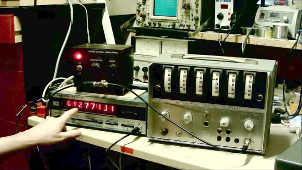
In the end, [Bob] settled for modifying the circuit while making the build look as close as possible to the original. He managed to track down the exact model of enclosure used in the original. The front panel is populated with a rotary dial just like the original, and the same neon lamps are used too, but as indicators rather than in ring buffers. Behind the scenes, [Bob] relied on 7400-series counters and decoders to make it all work — kudos for sticking with 1970s tech and not taking the easy way out with an Arduino.
The video below goes into more detail on the build and the somewhat kludgy operation of the machine, with a few excellent [Tom Lehrer] references and a nice Cybertruck dunk to boot.
Continue reading “Retro Calculator Build Proves The Space Age Isn’t What It Used To Be”