Logic Analyzers: Decoding And Monitoring

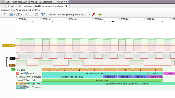
Last time, we looked into using a logic analyzer to decode SPI signals of LCD displays, which can help us reuse LCD screens from proprietary systems, or port LCD driver code from one platform to another! If you are to do that, however, you might find a bottleneck – typically, you need to capture a whole bunch of data and then go through it, comparing bytes one by one, which is quite slow. If you have tinkered with Pulseview, you probably have already found an option to export decoded data – all you need to do is right-click on the decoder output and you’ll be presented with a bunch of options to export it. Here’s what you will find:

2521888-2521888 I²C: Address/data: Start
2521896-2521947 I²C: Address/data: Address write: 22
2521947-2521954 I²C: Address/data: Write
2521955-2521962 I²C: Address/data: ACK
2521962-2522020 I²C: Address/data: Data write: 01
2522021-2522028 I²C: Address/data: ACK
2522030-2522030 I²C: Address/data: Start repeat
2522038-2522089 I²C: Address/data: Address read: 22
2522089-2522096 I²C: Address/data: Read
2522096-2522103 I²C: Address/data: ACK
2522104-2522162 I²C: Address/data: Data read: 91
2522162-2522169 I²C: Address/data: NACK
2522172-2522172 I²C: Address/data: Stop

Whether on the screen or in an exported file, the decoder output is not terribly readable – depending on the kind of interface you’re sniffing, be it I2C, UART or SPI, you will get five to ten lines of decoder output for every byte transferred. If you’re getting large amounts of data from your logic analyzer and you want to actually understand what’s happening, this quickly will become a problem – not to mention that scrolling through the Pulseview window is not a comfortable experience.

The above output could look like this: 0x22: read 0x01 ( DEV_ID) = 0x91 (0b10010001). Yet, it doesn’t, and I want to show you how to correct this injustice. Today, we supercharge Pulseview with a few external scripts, and I’ll show you how to transfer large amounts of Sigrok decoder output data into beautiful human-readable transaction printouts. While we’re at it, let’s also check out commandline sigrok, avoiding the Pulseview UI altogether – with sigrok-cli, you can easily create a lightweight program that runs in the background and saves all captured data into a text file, or shows it on a screen in realtime! Continue reading “Logic Analyzers: Decoding And Monitoring”

Logic Analyzers: Tapping Into Raspberry Pi Secrets

Today, I’d like to highlight a tool that brings your hacking skills to a whole new level, and does that without breaking the bank – in fact, given just how much debugging time you can save, how many fun pursuits you can unlock, and the numerous features you can add, this might be one of the cheapest tools you will get. Whether it’s debugging weird problems, optimizing your code, probing around a gadget you’re reverse-engineering, or maybe trying to understand someone’s open-source library, you are likely missing out a lot if you don’t have a logic analyzer on hand!

It’s heartbreaking to me that some hackers still don’t know the value that a logic analyzer brings. Over and over again, tactical application of a logic analyzer has helped me see an entirely different perspective on something I was hacking on, and that’s just the thing I’d like to demonstrate today.

Diving In

A logic analyzer has a number of digital inputs, and it continuously reads the state of these digital inputs, sending them to your computer or showing them on a screen – it’s like a logic-level-only oscilloscope. If you have an I2C bus with one MCU controlling a sensor, connect a logic analyzer to the clock and data pins, wire up the ground, launch the logic analyzer software on your computer, and see what’s actually happening.

For instance, have you ever noticed the ID_SC and ID_SD pins on the Raspberry Pi GPIO connector? Are you wondering what they’re for? Don’t you want to check what actually happens on these pins? Let’s do that right now! Continue reading “Logic Analyzers: Tapping Into Raspberry Pi Secrets”

Screenshot of Pulseview showing capture and decode of some digital channels

Need A Logic Analyzer? Use Your Pico!

There’s a slew of hardware hacker problems that a logic analyzer is in a perfect position to solve. Whether you’re trying to understand why an SPI LCD screen doesn’t initialize, what’s up with your I2C bus, or determine the speed of an UART connection, you’ll really want to have a logic analyzer on hand. People have been using a Pi Pico as a logic analyzer in a pinch, and now [pico-coder] has shared a sigrok driver that adds proper support for a Pico to beloved tools like Pulseview.

The specs offered are impressive. Compared to the $10 “Saleae” clone analyzers we are so used to, this thing boasts 21 digital channels with up to 120 MHz capture speed, 3 ADC channels at up to 500 KHz, and hardware-based triggers. The GitHub repository linked above stores the driver files out-of-tree, but provides build instructions together with an easily flash-able uf2 firmware. It’s likely that you’ll soon see this driver in a stock Pulseview installation, however, given the submitter-friendly attitude we’ve witnessed on the sigrok mailing list. However, if you need a logic analyzer ASAP, you should follow the caringly offered quickstart guide.

We’ve covered Pulseview being used in combination with cheap accessible analyzers before — a must-watch if you need to get yourself up to speed on the value they provide to a hobbyist. If an oscilloscope is what you need and a smartphone is what you have, perhaps you’ll enjoy the Scoppy firmware for the Pico.

We thank [mip] for sharing this with us!