
When navigating the vast and unpredictable expanses of outer space, particularly on the alien terrains of distant planets, smart engineering often underlies every major achievement. A paramount example of this is the rocker bogie suspension system. It’s an integral component of NASA’s Mars rovers and has become an iconic feature in its own right. Its success has seen the design adopted by the Indian space program and thousands of hobbyists in turn.
So, what exactly is it that makes rocker bogie suspension such a compelling design solution? Let’s dive into the engineering that makes these six-wheeled wonders so special.
Rock Yo’ Bogies
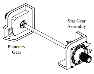
What’s great about the rocker-bogie design is that NASA isn’t afraid to share what makes it great. Part of the magic of the rocker-bogie layout is its simplicity. This innovative design omits the use of springs or shocks. Instead, picture a mechanical linkage that involves pairs of arms, termed as ‘rockers’, one on each side of the rover. These are connected with a differential pivot linking the left and right sides together. The rockers have a wheel at one end, and a “bogie” of two wheels that can pivot relative to the rocker at the other end. This basic six-wheeled layout is all there is to the rocker bogie system.
The brilliance lies in the differential’s ability to control the way the rover sits on the terrain. Due to the action of the differential between the left and right side of the rover, as one side of the suspension is pushed up, the opposite side is pushed down. This naturally spreads the load of the vehicle across all six wheels, which minimizes the maximum ground pressure on any one wheel. This is particularly desirable when traversing soft terrain, where excess ground pressure on one wheel can lead to it sinking into the ground. The differential action also keeps the rover relatively level, with the chassis maintaining an angle the average of the two rocker arms.
A major advantage of this design is its remarkable ability to scale obstacles up to twice the wheel’s diameter while still keeping all six wheels on the ground. This capacity allows duly-equipped rovers to effortlessly handle considerable boulders or fissures on rough terrain, while reducing the chances of getting stuck or losing traction. When approaching a vertical obstacle, a rocker-bogie rover first presses its front wheels against the obstacle. As the front wheel rotates, it lifts the wheel up the obstacle, and then crests it and rolls over. The middle wheel then does the same, with the bogie pivoting in turn, before the rear wheel completes the same journey. Forward progress is slow during such a maneuver, but a rocker-bogie rover can steadily work its way over these obstacles in a way altogether unfamiliar to other vehicle designs.
In NASA designs, it pairs the rocker-bogie suspension with high-torque actuators in the wheels. Combined with the suspension’s ability to keep all six wheels on the ground under most conditions, it provides the rover plenty of motive force to propel itself forward over even difficult obstacles. This also means that if a wheel or two are elevated or find themselves in a sandy pit, the rest can adeptly compensate, ensuring the rover continues its journey without hindrance. In the relentless and unpredictable Martian realm, this quality is invaluable, especially when a stuck rover could equate to a mission’s premature end.
The sheer simplicity and sturdiness of the rocker bogie system, with its avoidance of springs or shock absorbers, are commendable. This uncomplicated design translates to fewer components that could malfunction, offering resilience perfectly tailored for Mars’s challenging environment. Having less mechanical parts that can get clogged with dust, fatigue, or wear, is of huge benefit when your rover is on another planet far beyond any maintenance help.
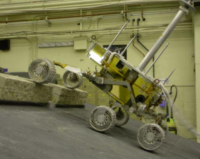
Roger Cheng’s Sawppy rover uses a rocker-bogie suspension design. Here, it demonstrates the suspension’s ability to tackle high obstacles.
The one area in which the rocker bogie design doesn’t really excel is in speed. NASA’s fastest Mars rover is Perseverance, with a top speed of around 0.12 km/h. As a guide, walking pace is a comparatively blazing 4 km/h. The slow speed is somewhat justified by the fact that there’s a huge time delay between Earth and Mars, making fast travel difficult to control. At the same time, the slow nature of the rovers helps reduce the mechanical complexity. The faster a vehicle travels, the greater the shock loads. Reducing shock loads by reducing speed reduces the need for dampers.
The rocker-bogie system has been copied many times over, a true testament to its engineering value. The Indian Space Research Organisation (ISRO) chose this very suspension system for its Pragyan lunar rover, which landed on the moon as part of the Chandrayaan-3 mission. The rover has ably navigated the difficult lunar surface without major incident.
Similarly, many makers have put the design to good use, with Roger Cheng’s Sawppy rover a great example of the form. The design demonstrates excellent obstacle climbing abilities. That’s due to Roger’s hard work in building a proper implementation of the rocker bogie design, with the crucial differential link between the two sides of the rover. Many builders of homebrew rovers try to replicate the six-wheeled design, but miss this key feature. It’s understandable, given the mechanical complexity of implementing the differential link, but a rover without it gives up some ability in turn.
(Editor’s note: On the day we’re publishing this, a new version of the NASA-JPL Open Source Rover hit our inbox! Check it out.)
If you find yourself hard at work in a government or private space program, and you need to build a rover, consider the benefits of the rocker-bogie design. If you’re going anywhere soft, bumpy, rocky, or treacherous, it could be the solution you need.


How about an 8 or even 10 wheeled version?
I mean you could just keep throwing down more and more yokes.
Look at the yoke setup for a ten mule team and… well that’s pretty much it, just being pushed instead of pulled.
Lunokhod
My favorite variation is the SHRIMP rover design with one wheel in front and one in rear.
This will come in handy earth-side for our next dystopia.
https://en.wikipedia.org/wiki/Landmaster
Oh glob, I hope Elmo won’t see this. ;-)
I was the advisor for the Continuum rover team which took part in the University Rover Challenge. Our rover had a “rocker” suspension: we used only four wheels and didn’t use the bogies. It still traversed hard terrain very well. As for the top speed, there is nothing precluding this design from going fast: our design was (as verified in an unofficial contest between teams) the fastest, reaching twenty kilometers per hour – on moderately flat terrain of course, but, thanks to a low center of gravity, the rover survived many mishaps without flipping.
That animated gif is incorrect: the rover body does not stay level on that terrain.
The text in the article describes the motion correctly though.
This is true! I was always under the impression that the point was to keep the body level, but it actually does pitch a bit. It’s much more to keep wheel pressure equalized.
(Things you learn reading Hackaday!)
Well, it’s supposed to be the average of the two angles, which is usually more level than the maximum of the two.
…. and also more level than the minimums.
If you’d like to define your units&terms that way.
I’d say it’s down to implementation details.
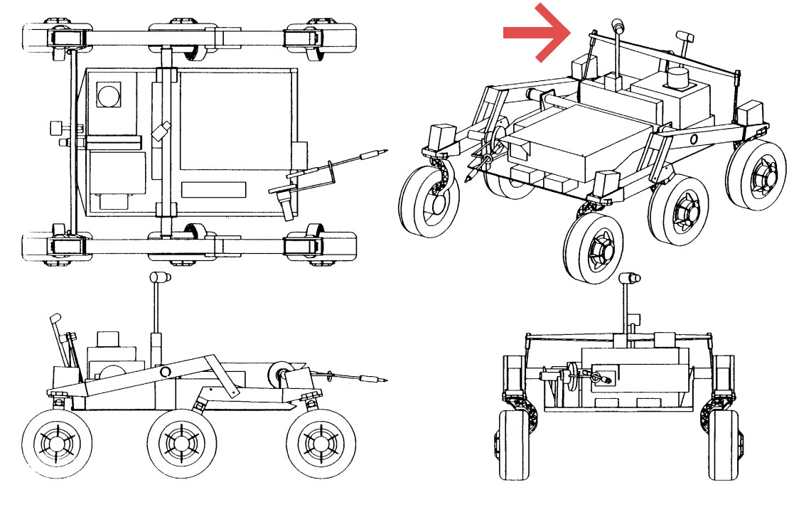
The center body could be free floating and kept horizontal by gravity. The big red arrow in one of the pictures is a way to keep the center to the average of left and right body. You could even ad an extra motor for active stabilization or tilting the body on purpose. It is whatever your needs are.
And indeed, the main goal is apparently to equalize wheel pressure, by varing the length of the leavers.
But I do wonder whether that is the optimal solution. Maybe a lighter pressure on the “front” wheels can help with getting over obstacles. But I guess they have done a bunch of experiments during the design of this thing. It’s quite easy to build a prototype with adjustable leavers, or just swap the levers for different lengths and run some tests to see how it goes.
The use of “to” in the title makes it sound as if “Extra Planetary Rovers” are the problem that needs to be solved and Rocker Bogie Suspension is what solves them.
Many ski lifts use an equal system to keep the pressure on the cable equal over all wheels, independent of cable output angle (which differs greatly with the weight on a section, on the whole cable, and cable tension) and the traversal of the “bulbs” where seats/cabins connect to the cable.
Very nice article! I’ve been working on a Sojourner replica for a while. I’m finding the most difficult part, so far, is how the differential arm connects to each side of the suspension. It looks simple at first until you realize the rocker flattens out for transport to Mars. In its stowed configuration, the differential arm is pushed to one side as if the rover were climbing over a large rock. So the lengths and angles of the brackets and how the brackets are attached to the rocker arms is really slowing me down. I’ll share a link to a video I made 6 months ago of testing the left side suspension after I made it:
https://www.youtube.com/watch?v=so4DkISAvVc&ab_channel=StrayRobotics
Lots more work to do. Currently I’m painting the right side parts to make them look like aluminum and then I’ll take apart the left side and paint that as well.
Fun fact, Don Bickler is the guy at JPL who invented the rocker-bogie suspension system. He came up with it after seeing his son’s rock crawling Jeep in the early 90’s. So when a rover was proposed for Mars, Don told management about his idea and rovers have been using the design ever since. Author, Jay Gallentine interviewed him a few years ago for an up coming book that he hopes will be out early next year. So be on the look out for that.
Thanks for writing this article! It’s so great to see other rover suspension nerds out there!
I don’t like finding fault, but I feel that this is remarkably low-quality for something from Hackaday. I’m sorry for being the one to say that.
Even the most superficial perusal of Wikipedia highlights the distinction between the earliest suspensions with a geared differential, later ones with a differential level acting in the horizontal plane, and the even simpler European mechanism.
Where did the vertically-acting differential level come from? Why wasn’t it used? Are there any disadvantages to the European approach? Does the Indian rover use one of the existing mechanisms unchanged or does it introduce its own ideas?
So many questions. So few answers.