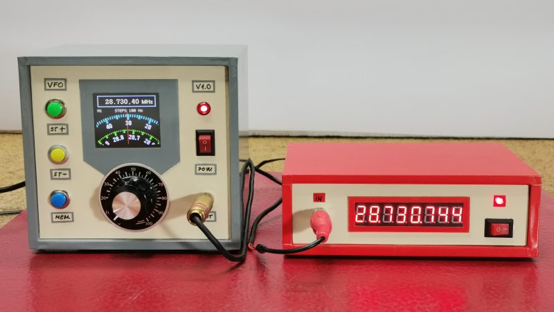
[mircemk] had previously built a frequency counter using an Arduino, with a useful range up to 6 MHz. Now, they’ve implemented a new design on a far more powerful STM32 chip that boosts the measurement range up to a full 30 MHz. That makes it a perfect tool for working with radios in the HF range.
The project is relatively simple to construct, with an STM32F103C6 or C8 development board used as the brains of the operation. It’s paired with old-school LED 7-segment displays for showing the measured frequency. Just one capacitor is used as input circuitry for the microcontroller, which can accept signals from 0.5 to 3V in amplitude. [mircemk] notes that the circuit would be more versatile with a more advanced input circuit to allow it to work with a wider range of signals.
It’s probably not the most accurate frequency counter out there, and you’d probably want to calibrate it using a known-good frequency source once you’ve built it. Regardless, it’s a cheap way to get one on your desk, and a great way to learn about measuring and working with time-varying signals. You might like to take a look at the earlier build from [mircemk] for further inspiration. Video after the break.


This kind of device is quite useful and this project is dead simple to build. The only problem is that the writeup is a bit weak. A beginner or even a reasonably intermediate user will have trouble reproducing it.
Suggestions:
Mention what kind of 7 segment display board it uses (it’s a MAX7219/7221 style).
The code is for the arduino environment but isn’t called “something.ino”.
Start a git repo, put the code in there and link to the repo. That will let you document the code better and have it named properly.
This is too useful and simple of a project to not let it be as easy to reproduce as possible. I lot of people could use a device like this. Author, if you need help with any of this, please reply and I will be glad to help you.
This is definitely a useful project, but if you want to push it even further then using a cheap FPGA (sipeed has decent cheap ones) would get you higher speeds, at least into the hundreds of megahertz. The tang nano 20k from sipeed has a separate clock generator chip on it which could make it more useful for a project like this.
Once you have the signal you want to count in a FPGA, you can do some clever things too.
I assume the arduino version is essentially – open a gate for a fixed time, perhaps a second, and count rising edges. In an FPGA, that can be augmented by synchronizing the opening edge of the gate to the fpga clock, then counting edges for the gate period. Then when the gate closes, time to the next rising edge. You can then combine the integer edge count with the fractional last period to get much better pulse resolution for those annoying frequencies in the middle. Where either counting pulses per gate, or time units per unknown cycle results in inadequate resolution.
I’d say that addition of even a small FPGA easily doubles or triples the total BOM cost.
Instead, any sort of counter (CMOS / TTL, ABT, etc) can very easily be added as a front end to extend it frequency input on the high side. And for frequency counters there are also prescaler chips with which the input can easily be extended to the GHz range. On top of that you can also simply use two timers to tap of the signal both after the prescaler (for measuring high frequencies) and before it (for measuring low frequencies).
Frequency counters like this are fun beginner projects for microcontrollers and it is quite easy to get 6 or more digits of resolution and accuracy. The latter would need a bit of careful programming (I have not looked at the code of this project). Resolution / Accuracy is mostly determined by the quality of the reference clock. If you want to see how far you can squeeze this, you can get second hand OCXO’s form Ali for between EUR10 and EUR20. and these have accuracies of nearing the single digit ppB area. Regular cheap microcontroller crystals are not very accurate. You can expect about 200ppm accuracy of those, combined with a lot of drift and temperature dependence.
An OCXO will have a warmup period but you could flash the least significant digits of the count in code, until that warmup time has passed. True, they are still much more accurate than crystals even on a cold start.
A neat idea that would not take much to have a better front end. I also have a question: did you design the VFO too? If yes then where are the details?
The VFO is described in one of his previous videos.
https://www.youtube.com/watch?v=KSovEpCmWY0
If you have an old PIC microcontroller in a drawer, you can build a frequency counter that easily doubles that limit. This is not doable with other uCs and the reason is how the PIC clock and internal dividers are built. Searching for “pic frequency counter” returns some interesting projects.
A possible further development could be to use the PIC only to count the input signal frequency, then translate it into serial data so that it can be displayed with any other system having a spare gpio input.
This is correct. Just by looking around you will find PIC16F628A with 3x 74AUP1G80GW dividers yielding 50/ 500 MHz capability. Also, the ability to output data for logging. Microchip’s App Note AN592 is an excellent starting point.
Also, these PIC chips seem to behave well for RFI/EMI–important if you have sensitive receivers around.
Consider adding a prescaler (74HC4020) and D-FF (74HC74). With only two free-running timers (one counting the high-speed system clock, the other counting the input÷n), the frequency can be calculated to arbitrary digits by the formula: frequency=(timer0*prescaler)/(timer1/system clock speed) where timer0=input÷n, timer1=system clock. This is called reciprocal counting. The gate (counting) time is a whole number of ticks occurring between the rising edges of the input÷n signal (approx. 1 sec wide) so the only source of error is from the last [fast] system clock tick. The number of valid digits will depend on the stability of the system clock. I believe it’s: 1ppm=6 digits, 100ppb=7 digits, 10ppb=8 digits.
I’ve adapted this project (https://www.instructables.com/High-Resolution-Frequency-Counter/) to a ATTINY84@16MHz with SPI-LCD and have had success up 25MHz input (I didn’t have a faster source). Using a 74VHC4020 with input÷2048 (vs current implementation input÷256) should be able to count to 200MHz!
You can get many digits of resolution without resorting to a faster micro-controller provided the signal to be measured is repetitive and unwanted noise is statistical in nature. Citing the venerable “Fundamentals of Time Interval Measurements”, Hewlett Packard Application Note 200-3, Page-8:
TI Averaging
Time interval averaging can be used to get resolution to the picosecond (10 –12 sec) region on a repetitive signal. Averaging operates on the assumption that the factors limiting resolution are random in nature and will tend to average towards zero. A counter needs synchronizers in gate circuits and a noise modulated clock to achieve TRUE TIME INTERVAL AVERAGING with accuracy and repeatability independent of the input signal repetition rate. The HP 5345A and HP 5328A with Option 040 Universal Module both have this true averaging capability.[1]
The problem with this approach is: More digits of resolution require longer measrurement time, and of-course the counter’s accuracy requires a caliibrated timebase, which creates a chicken-and-egg paradox.
* Reference:
1. Fundamentals of Time Interval Measurements, Hewlett Packard Application Note 200-3 (Printed in U.S.A. June 1997, Hewlett-Packard Company Copyright © 1997, P/N 5965-7663E)
https://ilrs.gsfc.nasa.gov/docs/time_interval_measurements.pdf