These days, when it comes to GPS devices the antenna is typically part of the package. But what better opportunity for [Pepijn] to learn how to make a GPS antenna from scratch for a badge add-on?
 A patch antenna is an antenna of a flat design, which [Pepijn] was going to put directly on a PCB. However, there was added complexity due to GPS being a circularly polarized signal, and that meant doing some research.
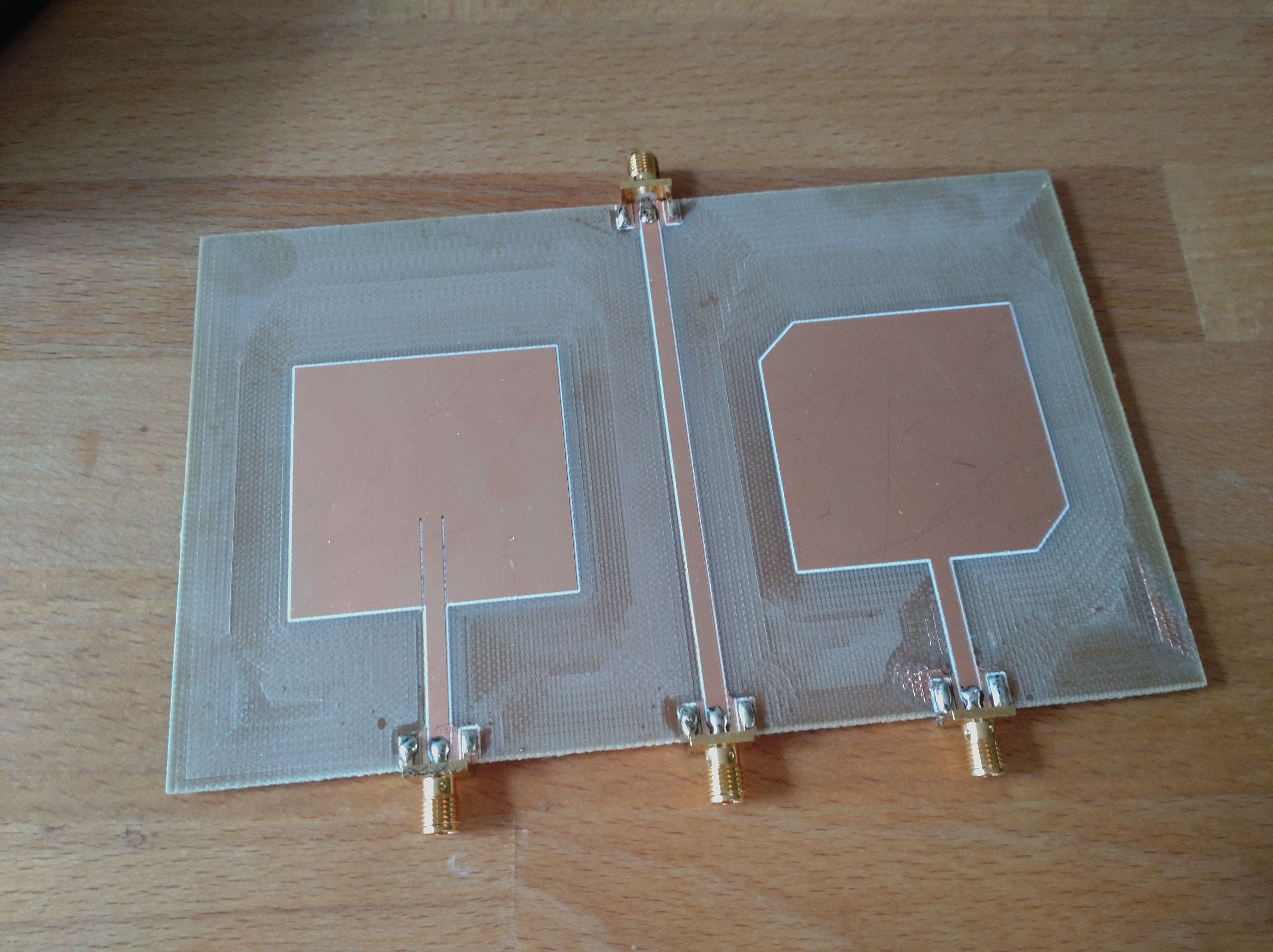
Sadly, nowhere did [Pepijn] encounter a straightforward reference design or examples, but in the end success came from going with a truncated corner patch antenna design and using simulation software to figure out exactly what dimensions were needed. (The openEMS free simulation software didn’t bring success, but the non-free Sonnet with a trial license did the trick.) The resulting PCB may not look particularly complex, but every detail matters in such designs.
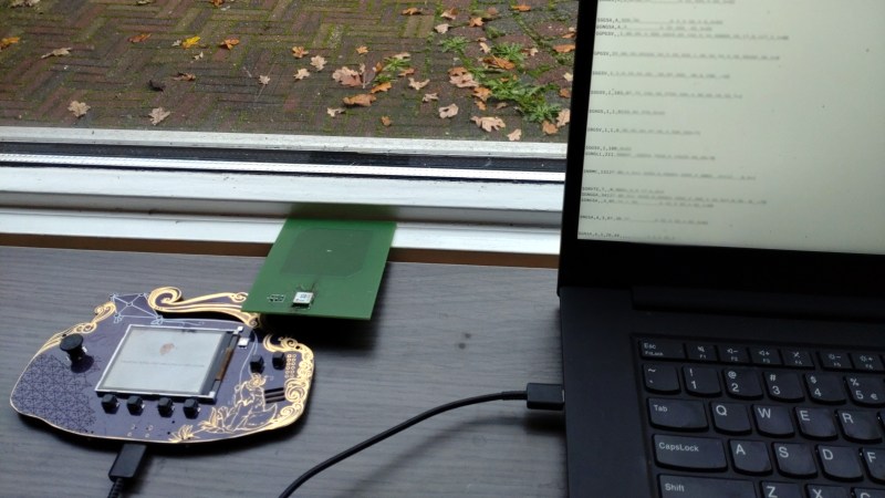
KiCad handled the PCB CAD design but the prototype came from cutting the PCB on a CNC machine instead of having it fabricated and shipped; a much cheaper and faster option for those with access to the right tools. A bit more testing had the prototype looking good, but the real proof came when it successfully received GPS signals and spewed valid NMEA messages. The design files are on GitHub but as [Pepijn] says, the project was about the journey more than anything else.


I’d be really interested in knowing why openEMS didn’t work out. I’ve done a few planar GPS antennas in my time using commercial full-wave simulators and the solution was usually straightforward. I’ve always heard good things about openEMS/Octave and this experience would be interesting to investigate.
He didn’t explain where the white bordering line on the PCBs came from.
I’d say the white lines are a side effect of milling the board. The white lines are along the edges of the copper. It looks like only the copper was milled away there, leaving a white surface. The larger areas were milled deeper, removing the lighter colored top layer.
It may also be that the edges around the copper weren’t milled straight. The bit may have been V shaped, leaving a slanted edge.
Yeah, cutting deeper with a V-bit is a common way to speed up the carving of larger areas.
I wonder if copper tape, cut to the right dimensions, would be equally effective?
Yes, check out a great video by VK2SEB on YouTube, he’s done pretty cool stuff with sticky copper tape.
In theory yes, but copper thickness has a LOT to say for impedance. Allso, the glue separating the copper from the fr4 using tape would allso affect it. I know the gig frequency rf filter magicians often prototype with tape, but I’m not sure if they use a special tape. I’ve been playing around with matlab antenna designer and reading up on design and matching, and to be honest, the more I learn, the less I understand how any rf design actually works in real life….
Thickness is not super important, but currents in a patch antenna are quite high at some points. The tape connections might be lossy.
I went to a maker fair in Austin (in 2007?) where a team was using a vinyl cutting plotter, normally used for making custom signage, to cut out fractal antenna patterns on peel and stick metallic film.
They were way down in the weeds on antenna theory and playing around with 3D arrangements of the various antenna elements. One of the coolest piece was an intricate fractal applied to the inside and outside of a clear acrylic tube. I have no idea how efficient it was but they were able to cram a lot more antenna into a smaller space using that method.
In the early days of WiFi and LinuxAP (linux router with a prism2 pcmcia card and a 66mhz processor with 1MB RAM), a friend professor at University of Louvain designed such PCB antenna for 2.4Ghz over FR4 substrat. I still have it somewhere in the basement :-)
I can say that a helix antenna tuned to the GPS frequency which ends up being about the size of salt shaker make the reception and accuracy improve unbelievably. I ordered some old radiosoundes and found one in them. I sawed it off the PCB and soldered on a SMA antenna connector and wow! But, you need to put it into a protective cover as the wires should remain very precisely positioned. I was very surprised by the performance over the standard ceramic patch antenna or onbaod PCB type.
This is a commercial GPS helix antenna that is often available on the surplus market for 20$ or so: GPS-TMG-26N (used to be much more available in the past, but you still find it). The filter in the LNA is quite narrow, only GPS L1 is let through, but the performance is very good near other transmitters, it is designed for cell sites.
I’ve been using Genesys Momentum to design various patch and slot antennas and it’s usually a “works the first time” process. A quadrafilar helix antenna is pretty hard to beat, performance-wise. You should be able to use the 4NEC2 EM solver (free) for this. There’s literature which gives a good description of 4NEC2 being used for 2.4 GHz helical antennas. This is getting close to the upper practical limit for 4NEC2 but you shouldn’t have any problems with a 1.575 GHz GPS antenna.
I need clock
What a blessing you guys are and just the medicine I needed to get back to DIY and Hacks. This will be a fun adventure for me.