We’ve all heard of the dangers of static electricity when dealing with electronics, and we all take the proper precautions when working with static-sensitive components — don’t we? But as much as we fear punching an expensive hole in a chip with an errant spark, electrostatic discharge damage isn’t the only kind of static hazard your digital designs can face.
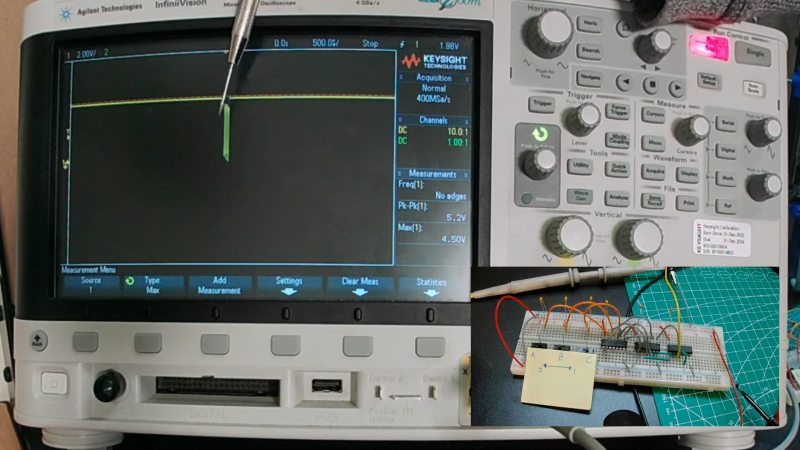
To be fair, the static hazard demonstrated by [Shane Oberloier] in the video below isn’t really an electrostatic problem. “Static” in this case refers to when a change to an input of a logic circuit gives an unexpected output until the circuit stabilizes. The circuit shown is pretty simple, with three inputs going into a combination of AND and NOT gates before going into an OR gate. The static hazard manifests as a glitch in the output when the middle input line’s logical state is toggled; according to the circuit’s truth table, the output shouldn’t change under these conditions, but the oscilloscope clearly captures a high-low-high blip. [Dr. Shane]’s explanation of why this happens makes perfect sense: the inverter on that input line has a brief but non-zero propagation time, putting the whole circuit in an ambiguous state before finally settling down to the correct output value.
So how do you fix something like this? This gets into the Boolean weeds a bit, and we won’t pretend to fully understand it, but at least for this case, [Dr. Shane] was able to add a single AND gate to sum the two other inputs and pipe the output into another input of the OR gate. That has the effect of canceling out the race condition caused by the inverter, but at the expense of a more complicated circuit, of course.
We found this to be a fascinating and informative discussion of a potential pitfall in logic design. But, if you still want to see some MOSFETs executed with static electricity, who are we to object?


Dealing with potential race conditions in logic circuitry has been around as long as logic circuitry has.
There’s a reason we got gray code too…
“So how do you fix something like this? This gets into the Boolean weeds a bit, and we won’t pretend to fully understand it, but at least for this case, [Dr. Shane] was able to add a single AND gate…”
Wrong! Your combinational logic must always be unconditionally deterministic and stable! If it is not – fix it properly. Adding a combinational or sequential logic element to “get rid” of the problem in the time domain may work, but it is bad practice.
People really ought to be taught about such fundamentals at university. Key search phrase: “bridging term”.
Associated concept in digital logic simulators is whether the simulator uses inertial or transport delays during simulation. One reveals static hazards, the other conceals them. I found that to my cost 40 (fourty) years ago, when one a subtle flaw.I my fully synchronous design almost caused a 3 month delay and a year’s salary NRE costs.
I studied Digital Design – we had this obviously – the thing is, this problem goes quickly away as you transition to more complex circuitry, which is almost always described in RTL. Everything is globally clocked, what happens between two clocks doesn’t really matter as soon as the clock is slow enough (and there is tooling for that) – than the race for critical path delay begins. You don’t want latches in FPGAs and pure logic without registers are kind of rare these days as well (when an MCU cost less than 74xx chip)
For some styles of synchronous design and implementation that is valid, but not for others. There can be traps for the unwary, as I found.
In my case the source of the problem was that FPGAs didn’t yet exist, so their primitives were irrelevant. That will still be true for implementations that exceed FPGA speed.
In the state of the art semi-custom process I used, there was one arithmetic operation that could not complete within one clock cycle, and so had to be spread over two clock cycles. No, pipelining was not an option.
Yes, when pushing technology it is often necessary to move outside the boundaries of bog-standard techniques. You have to be imaginative and inventive :)
Is this happening in a FPGA? Is something to think about and fix it, or the software suite make the necessary corrections? Or the LUT tables are to simple to create such race conditions?
In an FPGA you have always a combinatory section interleaved with flip-flops – registers, and the whole design is clocked and thus synchronous. What happens in the terms during switching is not relevant (and glitches may happen), but all comes to stable state when the next clock ticks. The delays of logic elements and interconnection paths are of course precisely tracked in the software and you know if the design is meeting the timing criteria for your target frequency.
When time gets involved things get weird.
It’s all kinds of wibbly wobbly.
“God created time so everything doesn’t happen at once.”–Albert Einstein (perhaps), and a lot of others…
“Time…it’s just one damned thing after another, isn’t it”–Winston Churchill
I remember in school doing discrete logic design and using this exact latency delay to create short pulses (invert the signal they are seeing in the video). If you wanted a longer pulse you could stack multiple inverters to get the desired delay.
The pulse is equal to the propagation time of the inverter.
If you picture every gate as having a delay time it makes a lot more sense about what is happening.
“…the inverter on that input line has a brief but non-zero propagation time…”
“…according to the circuit’s truth table, the output shouldn’t change under these conditions…”
“…This gets into the Boolean weeds a bit…”
The first sentence here, in a nutshell, explains the whole mystery behind this short piece (spoiler alert: there IS no ‘mystery’).
Every< electrical/electronic logic gate–or device (transistor; relay…)–has a propagation delay associated with it.
Logic design minimization via Boolean algebraic techniques (Karnaugh Maps and Truth Tables are simply visual means of manipulating Boolean algebraic equations) are all totally and completely disassociated with timing; have nothing to do with and are not dependent at all on any timing considerations. By extension, this means that Boolean Algebra can NOT be be used to account for problems which arise because of the physical characteristics of the hardware.
TL;DR–the ‘problem’ discussed here is not a problem of any form (type) of mathematics, but inherent in the mechanics of the medium used.
TL;DR #2–no better example than this is needed to explain why designers–who design with logic gates and flip-flops–design synchronous digital systems rather than random-logic ones.
It’s fun to have been around long enough for the old stuff to be new again.
But I’m not sure why the word “static” was used in the title. I guess the noisy switches are being confused with static electricity? Or confused with the effects of static?
In any case, yes, switches are noisy. And, with 3 asynchronous inputs and a delay line you’ll see all sorts of fun stuff (race conditions) if you don’t clean them up (or sync them to a local clock). And switches can be noisy in humid climes as well.
A useful trick used back in the day took advantage of this effect. Run an async signal to one input of an XOR gate, and the same signal thru a buffer to the other input of the XOR. The output of the XOR was then a short pulse for every input edge. Run a clean clock thru it and you get twice as many edges. Use a delay line and get longer output pulses.
Or use an AND gate and an inverter and get edges only on the input rising edge (one of the basic building blocks for basic de-bounce circuits).
Maybe the title was trying to hint at static-sensitive CMOS devices (in contrast to the logic static hazards described in the article)?
That was my take on it, at least.
Perhaps because the static logic works fine but once the logic becomes dynamic there is a problem.
Google “static hazard”, or look at https://en.m.wikipedia.org/wiki/Hazard_(logic)#Static_hazards
I find the gap between the understanding level of logic-circuit design between the comments versus the article itself to be fascinating.
But most interesting to me is that nobody with the deep understanding has explicitly provided the link with the most common exposure to this concept experienced by people without such a deep understanding of logic design (i.e. laypeople or the ‘average’ consumer with an interest in hacking electronics but not the education in logic-circuitry).
I know that for those of us with circuitry education this is PAINFULLY obvious, but for everyone else:
This is the whole reason that “clock cycles” exist and processor speeds are measured in frequencies, and that when we say “synchronous” versus “asynchronous” that the usage of such a clock signal is exactly what we’re talking about.
The toggling of the clock signal provides microprocessors a synchronized basis for the expectation that a reliable result of a given operation should have propagated to the result lines in a documented number of clock cycles per that operation.
This is why ‘overclocking’ speeds up the system at the risk of logic errors rather than overheating (though that can also become a concern, but is usually not the determining factor in the “standard” clock frequency.)
Thanks Dan. Enjoyed this immensely as it took me back to my TTL breadboarding days when I first got smitten with digitl electronics (still have tubes full of 74xx and 555s in the basement) and bitten by propagation delays.
I recall replicating the BCD-to-7segment decoder and the series of K-maps I made for each LED segment. In that situation, a static hazard would just cause a blip in one or more segments, but am sad I never learned of them at the time. Thanks for the excellent post!
This is one extremely good example of a logic-design situation where propagation delays of the logic used are irrelevant to the end result.
Another would be a closely-related project, near and dear to most all Hackaday readers’ hearts–the use of daisy-chained counters (divide-by-six/divide-by-ten) to build a time-of-day clock.
[It should be seriously noted that the upper-frequency limit of any daisy-chained-counter (random-logic) design is much lower than one built using synchronous design; and, somewhat as a corollary, the number of individual counter stages in an asynchronous design is very much lower than what could be achieved with a synchronous design. This is why all high-frequency counters, without exception, are synchronous. All these situations mentioned here are due to–you guessed it–propagation delay]
Thanks, Pete.