
Last time, I showed off a few ways you can convert an existing PSU to USB-C duty, and zoomed in on a particular way you can use to convert one of the ever-abundant 18 V – 20 V laptop PSUs to USB-C. All we have left is to write software for it, and I’ll explain how it works. There’s also that one cool USB-C secret I’ve found out, but you’ll have to read on to find out more.
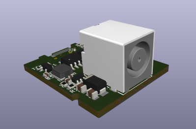
From the last article, we have a board that has an RP2040 and FUSB302 combo on it, which takes a 20 V DC PSU input from a laptop brick, and can switch either 5 V, 20 V or 0 V to its USB-C socket using FETs. The USB-C communication firmware is simple enough, but there’s caveats, especially regarding safety. Let’s go through those!
The Code Logic
VBUS has to be non-powered by default – we only supply 5 V when the FUSB302 detects a 5.1 kΩ pulldown on one of the CC lines. After supplying 5 V, we send out PSU capability advertisements, of the kind that we’ve learned to parse in the Replying PD article – and whenever we get a Request, we have to switch to the requested profile, connecting the voltage rail requested to the FET. I opt to not do any current consumption control in this design, assuming a well-behaved device, but you theoretically should do that. It wouldn’t be hard to add a high-side current sensor, say, something from Analog Devices – I just don’t want to do that now, especially given that I’m already using two of the exposed ADC pins to do Lenovo/HP PSU capability detection instead, one is used up for VBUS measurement, and the fourth is used for VIN (20 V rail) measurement – that’s four ADCs, which is as much as the RP2040 has got. However, if I ever need more ADCs, I can add an analog mux like 4051 in the next version!
 I also opt to not do emarker checks for cable 5 A consumption – in case you missed the emarker article, an emarker is an IC inside of a USB-C cable that contains data about the cable’s capabilities, including on whether the cable can carry 5 A safely. The PSU is supposed to do these checks before it may offer a higher-current profile, and I just haven’t yet looked into how to query emarkers. I can, however, detect the presence of an emarked cable relatively easily by merely detecting presence of the Ra (1kΩ pulldown) resistor that indicates a requirement for VCONN, and from that, assume that we have 100 W support for 5 A – 60 W-only cables don’t have emarkers in them unless they’re emarked as high-speed cables specifically.
I don’t own any 60W high-speed cables like that, and, you probably shouldn’t use such cables with such a device until you can add emarker check to the firmware. If there’s no emarker present, you have to limit advertised current to 3 A – thankfully, a device like a laptop will only take as much as it’s allowed to. Oh, and your board’s USB-C socket also has to be rated for 5 A: remember, many are only rated for 3 A.
On bootup, our code should check the capabilities of the PSU connected – for Dell PSUs, you have to read a One-wire EEPROM, and for Lenovo or HP PSUs, you have to read a resistor connected from the ID pin to either GND or VIN respectively, which you can do with a voltage divider and an ADC, plus a Zener diode for protection. In my opinion, if nothing is detected, I can pretty safely assume 3 A and go with that – laptop PSUs capable of less than 3 A are relatively rare. Then, we build a PD profile that contains our PSU’s voltage and current capability, and wait for a downstream device to get attached to our USB-C port. After that, we periodically send out a USB-C profile, and wait for a Request message – when we get that message, we parse it, sanity check it, then reply with an Accept message.
That Accept message will net us a GoodCRC response from the device – ideally, we provide 20 V only after we get it, so that we can be sure that the device has indeed acknowledged us being about to provide 20 V. Then, we can switch from 5 V to 20 V, and send our PS_RDY message to signal that 20 V is available.
Alternatively, you can do what I did and supply voltage after a short delay instead of waiting on GoodCRC – this deviates from the spec, but having a delay is Good Enough™. We also deviate from the spec in that we don’t start a “shut off VBUS” timer as soon as we get a Request message – this timer is a specification requirement for PSUs to implement, and it can trip you up if you don’t account for it while writing your own PD trigger code, but here it’s not 100% required. There’s surely a few more things here and there that we’re missing to be more spec-compliant and perhaps compatible with a larger amount of devices – but it won’t actually cause any problems!
Things To Watch Out For
There are, of course, some safety requirements that we can’t skip out on. For a start, we’re using the FUSB302B PD frontend, and it applies 5.1 kΩ pulldowns to its pins when it’s not powered up – this feature is known as “dead battery”, fairly self-explanatory. We, obviously, have to disable the pullups if we want to act as a USB-C PSU, and instead enable pullups indicating a 5 V / 1.5 A profile instead, as part of USB-C analog PD signalling. Both of these are super straightforward to do in software with the FUSB302, but there’s a catch – if you plug a USB-C PSU or a dual-role port into this adapter while 20 V is not yet supplied and our code is not yet running, it’s going to bootloop. We can detect this condition in our software, thankfully, and just wait until 20 V is connected. There’s also the FUSB302T version that doesn’t have the dead battery feature enabled, so if you are to build a professional USB-C PSU board, it will have to use the 302T version. I’ve already purchased some 301T ICs, now I just need to solder them on in place of the 302B. In our code, we can distinguish between -B and -T versions of the chip by reading the version register of the FUSB302, which helps!
 As soon as the 5.1 kΩ pulldowns are removed, we have to bring VBUS back to 0 V state, making sure that 20 V never stays on the connector after you unplug the device we’re powering. If 20 V is left connected to VBUS after the device pullups are no longer detected, this could result in 20 V getting on pins of a USB-C device that’s only okay with 5 V when you plug back in. This is the kind of safety-critical thing where you’ll want to use the watchdog timer – I’ll look into the MicroPython watchdog implementation, making sure that if my code crashes, the system will be reset into a safe state.
Oh, and of course, overcurrent protection is wonderful to have. To protect against shorting out the 5 V rail, in case the device you’re powering has a VBUS short, I recommend you use something like the SY6820 current limiting switch right before the 5 V FET pair input, setting it to a bit over 1.5 A. The previous schematic doesn’t have that, but the new one does! As for DC input overcurrent, you can try and set that, but I personally prefer to rely on the upstream PSU’s current limiting, and making sure that our device isn’t the weak point. Additionally, if we measure both VBUS and VDC, and if our resistor dividers are calibrated enough, we can measure current by measuring the difference between VBUS and VDC, using the FET as a current shunt. If there’s more than a few volts falling on the VDC-VBUS path FET, it might be worth disabling it.
Meeting Reality, Gradually
Even with these precautions, the code itself is not tricky. The FUSB302 provides interrupts for USB-C events, and we only need to react to these interrupts and any incoming PD messages in the FIFO. I’ve written a piece of code that constructs USB-C PD profiles out of a list – it’s just, the PD profile parsing function that we wrote in the “Replying PD” article, but it’s turning values into bytes instead of extracting values out of bytes. Since I already have the parsing code, I added a short check that puts the newly constructed profiles through that parsing code and assert()‘s that the results match! Constructing PS_RDY and Accept messages is easy – I’ve got a generic function that can send any command message already, that I made out of the Request function we wrote back then too.
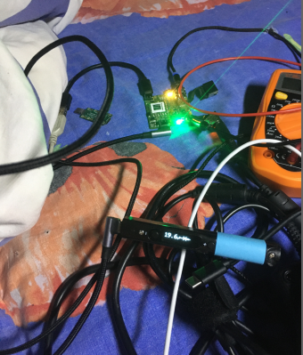
I’ve developed the PSU behaviour loop code gradually and tested it all throughout the development, starting tests with simple USB-C devices. For instance, when testing the basics of attach-detach behaviour and FUSB302 interrupt handling, you could use a random USB-C breakout that has 5.1K pulldowns on it – then, nothing is at risk of burning up if you accidentally supply 20 V. I’ve started testing this code with my Pinecil as it’s a pretty lenient USB-C device, in that its open-source PD sink stack works with a wide variety of PD supplies despite the quirks – which is wonderful for a device likely to have quirks and sharp edges! It also is a very safe device to test things on – it won’t care if you just put 20 V on VBUS, whereas quite a few laptops will object to that, and some might even have a fiery response.
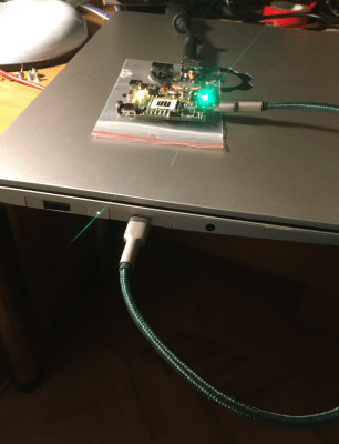
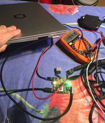 With the Pinecil, I could test all the basics – attach-detach behaviour, PD profile sending, and its PD tester features have shown me that it correctly recognizes all the profiles that my code creates! The final frontier was making this PSU work with my Framework laptop, as that was what I was actually developing this PSU for. Of course, it didn’t work on the first try – Framework uses PD controllers that have a proper USB-C stack with all the USB-C spec’s constraints enforced, so, some extra debugging was needed. The PD trigger code from the “Replying PD” article in particular has helped me iron out differences from the spec – I could plug my USB-C sink code board into the same board with PD sink code, see the UART output from both RP2040s, and compare my board’s PD communications to those of USB-C chargers I’ve had laying around.
There were two things I’ve found that seem to have been making the Framework’s PD controller sad. The first was that I was apparently sending the PD advertisement way too early after attach, which I figured out after noticing that it takes my Pinecil about five seconds to negotiate with my PSU, yet only about one second to negotiate with a charger I had laying around. Seeing that, I realized that my first advertisement was being sent way too early for the Pinecil to boot up and receive it, and tweaking made for negotiation that seemed instant. Having fixed that, the laptop would receive the profiles correctly and request the 20 V one, but it would detach after getting 20 V onto VBUS. The culprit there was me not waiting enough time between sending Accept and putting 20 V onto the bus – increasing the delay fixed that. It would’ve helped if I waited for that GoodCRC response instead, but, it felt okay to cut this corner at the time!
Reaping The Fruits Of Research
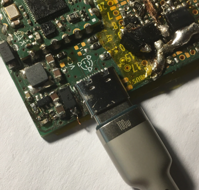
It would’ve helped if I were to read the specs and implement all the PSU’s constraints properly, going through the state machines and abiding by time constraints and all. Nevertheless, this PSU works wonders, and I’ve hardly had to check the spec as I developed this – which did wonders for my self-esteem! Even increasing the current to 5 A has worked out without a hitch, I’ve only had to make sure that I’d plug a 100 W-capable cable in, as the profiles are for now hardcoded. Yeah, there’s TODOs – my current code doesn’t yet have the emarker check, or laptop PSU capability check, so I’m advertising hardcoded PD profiles instead of calculating them on boot as I ought to. I’m working on these things slowly, and for now, it’s good enough for long-term testing with my laptop given a certain laptop PSU and cable combination. The first 100 W USB-C PSU I own, is the 10 0W PSU that I’ve built myself, and it feels nice.
 All of the code is in MicroPython as usual – it’s my choice for high-level tinkering-friendly implementations. You could simplify the code, port to C and put it onto a smaller device like an ATTiny or the CH32V003, since you only need a few GPIOs, ADC and I2C. That’s all you need to build a cheap retrofit adapter to make a USB-C PSU out of any DC PSU with a voltage that vaguely fits a USB-C profile – or not even that! Remember the secret I mentioned? I was offering 5 V and 20 V profiles in my code, but I was sending the 20 V profile with a 19 V PSU connected, since that’s what I had on hand. That worked on my Framework, and that made me wonder – just how non-standard of a voltage could I actually offer? I tried offering a 19 V profile, and to my surprise, the laptop accepted and started charging – at 95 W, no less. This is a big victory, dramatically increasing just how many different DC PSUs I can actually use this board with.
Making a custom profile with a voltage significantly above 20 V is likely not a good idea (not that I won’t try a 21 V LiIon pack sometime soon), but going below should be just fine! Of course, there’s caveats – for instance, some Framework motherboards still have the hardware bug with 15V handling, that needs a FET swap to have sub-18 V voltages work well. However, after the FET swap, this PSU lets you use any 10 V – 20 V DC source above 15 W to charge a Framework – you only need to communicate the voltage and the current consumption limit; with other laptops, your mileage may vary, because this might depend on the PD controller firmware. The gist is – if you want to charge your Framework from four or five 18650 cells in series, you can just connect them to VIN of this board, measure their total voltage on an ongoing basis, and periodically re-advertise available current and voltage on the fly as your pack voltage drops.
As it goes, I’m planning to package this circuitry into a few different formats, making sure that common types of DC PSUs are not cast aside! Also, given that the new Pi 5 expects a PD handshake in order to actually accept 5 A at 5 V, this article’s work might just help you power your Pi from a random hefty non-PD 5 V PSU without having it throttle. Though, they might’ve kept the 5 V GPIO header backpowering loophole, so I suppose we’ll have more details about the Pi 5 PD requirements once someone actually looks into it.
 This is not even all – a few of my friends have been tinkering with USB-C PSU designs in the meantime, turning my schematic into wonderful boards! For instance, here’s a board from [Wificable] that is a Framework laptop expansion card, which lets you use Dell and HP PSUs as USB-C chargers. In the future, we could add support for things like MagSafe into it!
This design has been fun, it gave me a way to reuse a whole bunch of PSUs, helped me find an unintended Framework PD controller feature, and will likely help me build a seriously straightforward and efficient USB-C powerbank for direct LiIon reuse. In addition to that, it looks like this card will lead to a good few designs on its own! I hope you’ve enjoyed this journey as much as I’ve enjoyed documenting it, and whenever you need to navigate the world of USB-C tech, hopefully these articles can help you.


This is awesome!
However a correction is in order. 45W power supplies from the large OEMs are extremely ubiquitous (~2.31A with Dell and HP, 2.25A with Lenovo, ~2.37A from Asus, Dynabook/Toshiba and Acer).
And I would recommend you to check QGeeM’s 60W 10Gbps USB-C-to-C cables, as they are the best cables I have found at a budget (and as I have made sure not to purchase any USB2 USB-C-to-C cables, except for Silicone ones (such as from Pine64, for my Pinecil), we have a few that are going strong here (and testing them with my USB-PD tester has shown promising results, although I have not yet tested whether it has a USB-PD marker).
Ye that fits my scenario still! Asus/Toshiba/Acer tend to have weird barrel jacks (=> can’t easily plug in, and can check before connecting), and with Lenovo/Dell/HP, you can already check for 45W with the ID pin. If I were to make a “random laptop/other PSU reuse” with tons of barrel jacks, I’d likely have a potentiometer that’d let you input a max current setting, and a “confirm” button!
As for QGeeM, thank you, noted! I mostly buy USB2-only C-C cables, 60W and 100W, because I use a ton of USB2-only devices and USB-C chargers, and I just can’t justify the extra thickness of four high-speed pairs. That said, I should get a few more USB3-capable ones for sure, and it’s lovely to have a recommendation! Also, yes, the Pine64 C-C cables are super lovely^^
That would absolutely be a dream.
Yeah, I use USB3 just as much as I use USB-PD (a UGREEN 2.5″ HDD enclosure, I make sure that my phone supports USB3, enclosures for M.2 modems, etc.), so I actually need it.
I wasn’t satisfied with a couple of QGeeM’s adapters. I recommend UGREEN cords instead.
I too recommend UGREEN’s power supplies over QGeeM’s, however from my testing, UGREEN simply does not have a USB-C-to-C cable that can stand it’s ground against QGEEM’s offering (and this is pretty much the only QGeeM product I recommend).
My current recommendations for cables (since BlitzWolf no longer produces their legendary AmpCore Turbo cables any longer) are as thus:
USB-A to microUSB: IKEA
USB-C to USB-A (USB3): A specific generic cable, with expectations that you cannot trust that every unit will be good.
USB-C to USB-A (USB2): IKEA
USB-C to USB-C (USB3+60W): QGeeM
USB-C to USB-C (USB2+60W): IKEA
USB-C to USB-C (USB2+Silicone): Pine64
USB-C to USB-C (100W+USB2 or USB3 or TB): Currently looking, however I do not have anything that can benefit from it. Until I know for certain, my main recommendation is Apple, however UGREEN seems to have decent USB2 cables.
USB-C to USB-C (USB3+100W (or was it 230W? I forget)+Silicone): A certain Chinese cable that someone in the Pine64 forums (Pinecil subforum) linked to an AliExpress listing of.
By the way, a safety recommendation for those who travel a lot, and/or live in a country that officially accepts Europlug plugs, but does not use hexagonal sockets (which are the only ones that provide proper weight support for Europlug devices, though German “Schuko” do semi-provide that, and with “PinFix adapters even better):
UGREEN’s (and Anker’s 20W Nano Pro, which is the only power adapter I am aware of with a built-in plug that is small enough to be used with an IP66 socket while latter is closed) USB-PD power supplies in their British BS1363 variants are particularly useful, on account of their shape, which allows better weight distribution, and those coupled with compliant adapters, are absolute lifesavers. Those, or just get (or make) a USB-PD power supply that either has grounding (or at least grounding pins/contacts), and/or has the plug on a cable, rather than built-in.
The board has a nice “rework” job. Reminds me of those river tables
Thank you! The devboard has served its purpose thoroughly, and I can’t help but imagine it to be a very happy board ^w^
If you can get into 24/48v territory, there’s a viable use-case in 3D printing. First up: toolhead. I’d love not to use CAN. USB-PD 3.1 EPR supports 48v/240w. That’s more than enough for any toolhead I can think of!
What would be the advantages? I’d love to hear more about it, and, I’m very interested in how it could actually fit!
This sounds like an interesting concept. There are already those CAN toolhead boards, but IIRC, they require an extra power source. I’m sure it would be possible to run PD and USB2.0 over a USB-C Cable, to both power and command the toolhead. 100W at 20V should be plenty to work with for a lot of printers (slower heat-up time on 24v heater cartridge).
The main advantage would be that it’s a single cable solution. No more ‘ugly’ bundle of cables from your mainboard to your printhead, just a single USB-C cable.
On top of that, you could swap toolheads by just unplugging the cable!
I could see this being accomplished with a custom toolhead PCB, and Klipper firmware.
There are some side benefits to this as well – such as being able to enumerate capabilities via USB as well. You could grab a toolhead in any position and instantly grab its nozzle size, nozzle length, offsets, etc. I’ve been pushing this idea everywhere I can for years, and it just seems like now some people are finally starting to agree, so I’m very happy to see this conversation pop up without intervention for once :)
Hmm, fascinating, had this sort of approach on the back burner as some USB-C to OBD especially the simple one from a paperclip check engine light flash test such as on the Opel/Barina/Corsa etc
Time to get up to speed on this one, see a couple of potential product protos on the cards,
Thanks for posting :-)
Yes, this is product-izeable enough ^^ A friend of mine is making a “what’s this USB-C port” tester, which checks for altmodes and PSU capabilities, and my code will let them test for “which profiles are requested by this phone”, too!
Great article ! Is there a link to this schematic ? Thank you.
Thank you! I should revise it and put it up somewhere online pronto, tbqh!
https://github.com/oxplot/fpx
Another cool one that hackaday has hosted
https://hackaday.com/2021/04/21/easy-usb%E2%80%91c-power-for-all-your-devices/
Ye it’s a lovely project! It’s a different side of the equation, however – basically a trigger board, and this effort is a USB-C PSU that you could plug a trigger board into!
A slightly different note than one from the first article. The reason I am curious about the 240w profile is I pre-ordered the Framework 16 DIy with the video card expansion bay, and I opted to bring my own PSU. While the 180w will work for the most part Framework does mention that full load will be approximately 240w. The expansion card that your friend did would be interesting to replicate.
Yep, that’s the whole reason I stumbled upon this article. If only I could read, I wouldn’t buy the FW 16 without their power charger. And because it uses USB PD there is no way that I can use my 300w slim tip Lenovo charger on both hardware and software levels. That’s really sad because I expected it to be “anti proprietary” laptop that will be easily repairable as well. Guess I have set my hopes too high…