I’ve talked a fair bit about USB-C before, explaining how it all works, from many different angles. That said, USB-C is just the physical connector standard, plus the PD part that takes care of voltages and altmodes – things like data transfer are still delegated to the two interfaces you invariably end up using on USB-C ports, USB 2, and USB 3.
You might think USB 2 and USB 3 are tightly related, but in many crucial ways, they couldn’t be more different. I have experience working with both, and, as you might guess, I want to share it all with you. You might be surprised to hear there’s plenty to learn about USB 2 in particular – after all, we’ve had it hang around for 30 years now. Well, let’s make sure you’re fully caught up!
The Ingredients
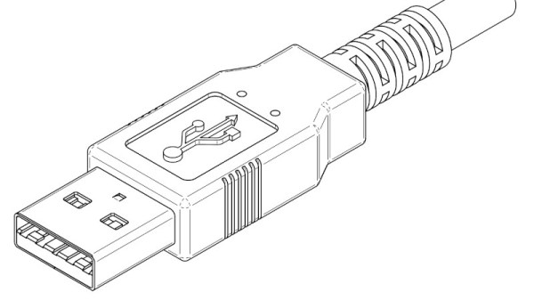
USB 2 is a point-to-point link – one side is “host” and another is “device”, with the host typically being a PC chipset or a single-board computer. USB 2 relies on a single pseudodifferential pair. It’s “pseudodifferential” because the wires don’t just do differential signaling – they also use digital logic levels and pullup/pulldown resistors to signal device presence, especially in the beginning when the USB link is still getting established. Indeed, you can imitate a USB device’s presence with just a resistor.
Continue reading “Ubiquitous Successful Bus: Version 2”


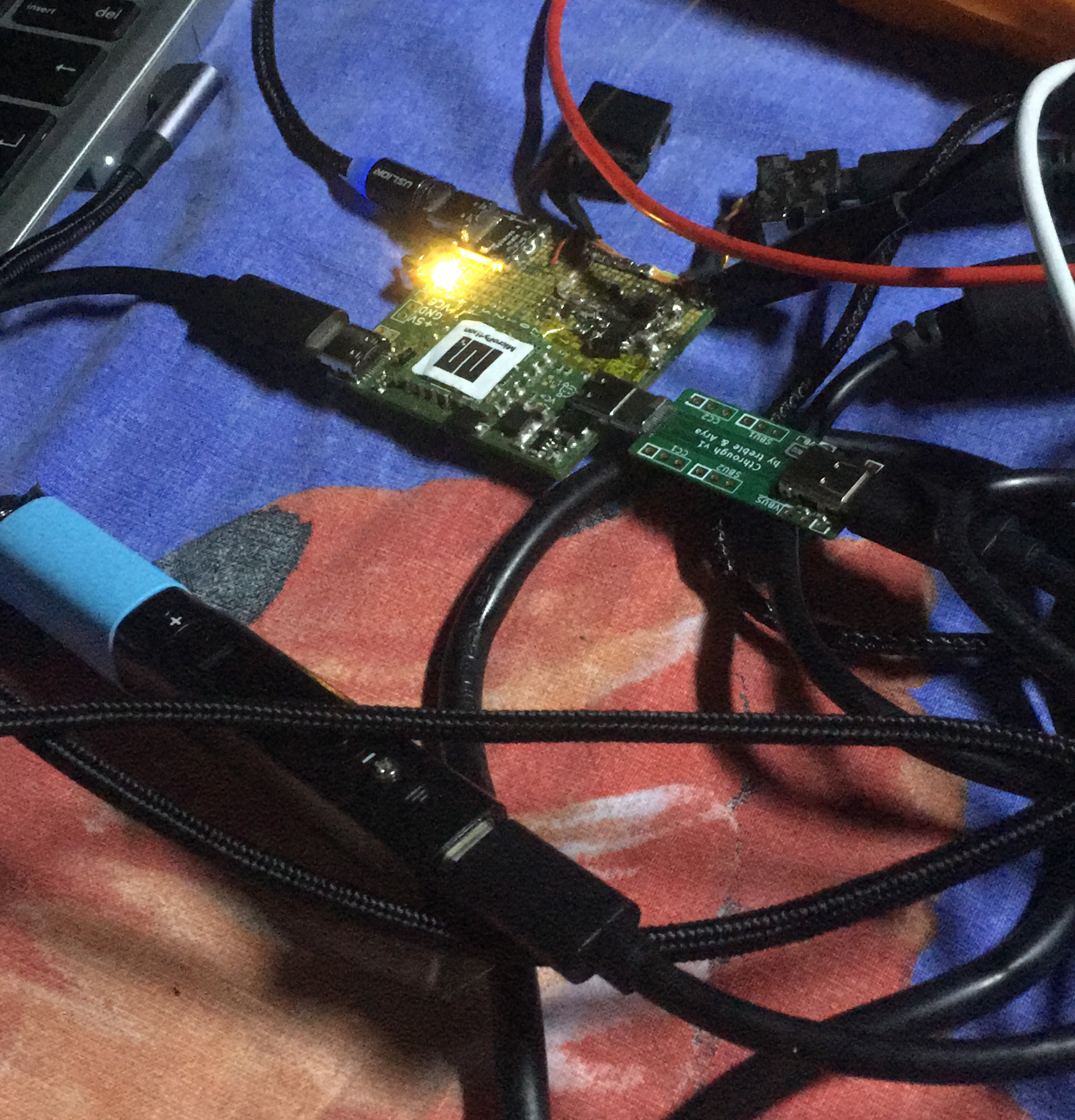
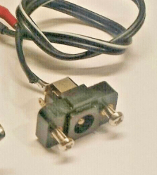 This board’s idea is thought-out and executed well – it replaces a bespoke barrel jack assembly, and is mechanically designed to fit the screw holes and the free space inside the chassis. For USB-PD, it uses a CH32V003 coupled with FUSB302 – I definitely