There’s no denying how useful surface mount technology is, and how enabling the ability to make really small circuits has become. It comes at a price, though; most of us probably know what it’s like for the slightest wrong move to send a part the size of a grain of sand into another dimension.
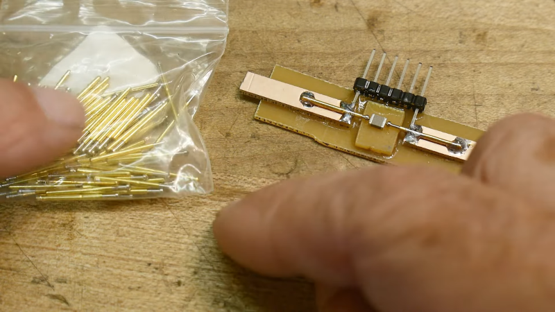
To help make testing these parts a little easier, [IMSAI Guy] has come up with this clever little SMD test fixture. It’s designed to hook up to another custom board, which in turn connects to a wonderful old Hewlett-Packard 4275A LCR meter. The jig is based on two pogo pins mounted directly across from each other on a scrap of single-clad PCB. The spring-loaded contacts, which short together when not in use, are pulled apart to load an SMD part, like the 1-μH inductors shown in the video below. The pins hold the component firmly and make good electrical contact, allowing hands-free testing without the risk of an errant touch of the test probes sending it flying.
While the test fixture works well for larger SMDs, we could see this being a bit fussy for smaller parts. That would be easy enough to fix with perhaps some 3D-printed arms that retract the pogo pins symmetrically, holding them open until the part is loaded. A centering fixture might help too, as would a clear shield to contain any parts that get the urge to go for a ride. But, for the tactical application [IMSAI Guy] has in mind, this sure seems like enough.
Just getting into surface mount? If so, you might want to check out this handy guide to the often cryptic markings used on SMD parts.


My big fingers wouldn’t be able to handle something like this very well. Ingenious for those who can handle such a setup, though!
Once you get to Tony enough SMD parts, would it be easier to have larger contacts? Maybe a couple of layers of metal tape on some 3D printed jaws? A button to spread them, and be lightly spring-loaded?
This is a quite simple start for a text fixture, and it’s quite easy to make it a bit easier to use.
Instead of gluing the PCB to the big carrier PCB, you can sand slanted edges to it, and then fix some strips to the side too. Make a dovetail just like in the compound for a lathe, and add an extra spring (or a pogo pin pointing the other way). And then:
1. Hold it horizontal.
2. Slide it sideways.
3. Drop in a SMT part to test with your other hand.
4. Let it slide back gently.
That HP247A is quite a beast. Also like the BNC fixture with the (3D printed?) levers.
Reminds me of the Red Pitaya. It’s so strange they put the BNC connectors on that thing under weird angles. That makes impossible to add a text fixture to it. (It only works with cables).
I just hold it down with a toothpick, also the cut end of a paper cotton swab will stick well to SMD devices. I usually jam it on one side, leaving the other side free to solder.
Put the toothpick in one of those little “helping hand” devices and let the weight from that hold it in place.
Another option for getting contact with the part might be to leave it in the package and pierce the package to measure.
Appreciate the hack, I will file it for future use. I love a good hack XD.
I really like this jig design!
Anyone got idea/tutorials how this could be extended to 2-port/kelvin version and support even smaller SMDs?
For smaller SMDs, tweezer probes work quite well. Though the capacitance/inductance from long cables can be a problem.
Something like this seems cool but pretty expensive:
https://smarttweezers-store.com/products/st5s-set
You can buy a kit to make similar test tweezers for much cheaper:: https://www.siliconchip.com.au/Shop/20/6631
I made a pair and I love them. Mostly I use a “real” multimeter, but the tweezers are great for doing quick tests during SMD assembly. Is that anonymous black 0603 the 100R or the 10k resistor? Grab it with the tweezers and check. Is that a cap or an inductor? Grab and check. It also has rudimentary scope functions, which is good for e.g a quick check for presence of serial, clock signal etc.
I really like these accessory fixtures for this kind of work.
https://www.omicron-lab.com/products/vector-network-analysis/accessories/impedance-test-fixtures-b-wic-b-smc
you can get off brand one’s for like 30 bucks on amazon and they work reasonablly well, not quite as quick but they work
Or, make a pair of tweezers that (optionally) locks closed and has each tip wired to a different probe.
Pick up the part and let it hold it while the measurement happens.
Or, don’t use the lock, and do a bunch of parts one after another while you hold it.
Or just buy a pair of SMD test tweezers that’ll plug right in to things. Look to be <$10 on the Bezos Barn.
If you want to use a device as in the video and adjust settings through rages with buttons then a tweezer miht be not the best option.
Especially not if you have unsteady hands like this guy.
I found the going through ranges interesting since you would not normally do that with SMD components but when you think about it SMD components might be trusted too much; and also have some unknowns that you don’t know about because one just assumes it’s the same as what’s printed on tthe package +TheSameCaveatsAsThroughhole
The part is more likely to fly being trapped between to spring-tensioned pins !
I personally use a piece of silicone adhesive (“gecko” tape). It´s sticky without leaving glue behind, can withstand some heat or at least enough that one can quickly solder magnet wire. It´s very forgiving and easy to handle.