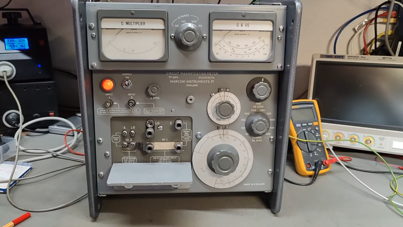
[Thomas] picked up a Marconi TF1245 with dents and dings. We have to admit that we had not heard of a “circuit magnification meter,” but apparently, this was a thing in the late 1960s and early 1970s. Turns out, we have heard of this kind of meter before, but it was called a Q meter. The device works using a very low-impedance resonant circuit and a very high-impedance voltmeter. It measures the ratio of the voltage across the known circuit and the unknown circuit. This particular meter needs an external signal source with very special characteristics. You can see the well-built device in the video below.
The unit didn’t seem to work, but we suspect that it didn’t like his normal signal source. According to a comment in the manual, the matching signal generator delivered 0.5V into a 0.5 ohm load. You could also use a matching transformer to get to the required match.
Like anything made by Marconi, the build quality is amazing. There are four tubes and four diodes inside, along with beautiful meters, transformers, wafer switches, and some amazing mechanical linkages. As far as we can tell, if [Thomas] had a matching transformer, the device would work.
Of course, there were other Q meters. You could measure Q with a grid dip oscillator, too.


Very nice builded instrument.
I believe that you should apply a real inductor to have a mesurement. THe green wire is not a “real” inductor.
Refining my previous post. The instrument is done to measure the magnification of a resonance circuit.
I believe that so see any significan output, a serial or parallel LC circuit should be applied at the input.
That is a very cool looking unit. Now I will be watching for one :-)
At resonance, the voltage across either one of the components in a series LC is the source voltage multiplied by the Q. Thus, if you have 100 volts AC across an LC with a Q of 20, the voltage across the C (or L) will be 2000 volts.
Similarly with current in a parallel LC circuit: current is drive current multiplied by the Q, and goes through the components alternately.
Thus, the Q “magnifies” the apparent AC voltage across either component, and the device is measuring that magnification.
It’s really hard to build a high-q resonance, but it happens occasionally. A Ham that puts a coil in series with an antenna to make it appear longer will sometimes transmit at the exact resonant frequency of the LC combination, building up enormous voltage on the L component and burning it out.
The voltage (current) multiplication at resonance is a phenomenon that I think few people realize. It’s how Tesla got long bolts of lightning from his coils, while modern designs simply consider them as big transformers and have to install pins on the top bell to get any sparks. That’s not how it’s supposed to work, and if you build a high-Q resonant circuit you can get the long bolts.
That was a very interesting comment, thanks!