Funny things can happen when a security researcher and an electronics engineer specializing in high-speed circuits get together. At least they did when [Limpkin] met [Roman], which resulted in two interesting hardware solutions for side-channel attacks.
As [Limpkin] relates it, the tale began when he shared an office with [Roman Korkikian], a security researcher looking into current-based attacks on the crypto engine inside ESP32s. The idea goes that by monitoring the current consumption of the processor during cryptographic operations, you can derive enough data to figure out how it works. It’s difficult to tease a useful signal from the noise, though, and [Roman]’s setup with long wire runs and a noisy current probe wasn’t helping at all. So [Limpkin] decided to pitch in.
The first board he designed was based on a balun, which he used to isolate the device under test from the amplification stage. He found a 1:8 balun, normally used to match impedances in RF circuits, and used its primary as a shunt resistance between the power supply — a CR1220 coin cell — and the DUT. The amplifier stage is a pair of low-noise RF amps; a variable attenuator was added between the amp stages on a second version of the board.
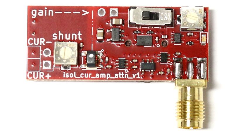
Board number two took a different tack; rather than use a balun, [Limpkin] chose a simple shunt resistor with a few twists. To measure the low-current signal on top of the ESP32’s baseline draw would require such a large shunt resistor that the microcontroller wouldn’t even boot, so he instead used an OPA855 wideband low-noise op-amp as an amplified shunt. The output of that stage goes through the same variable attenuator as the first board, and then to another OPA855 gain stage. The board is entirely battery-powered, relying on nice, quiet 18650s to power both the DUT and the shunt.
How well does it work? We’ll let you watch the talk below and make up your own mind, but since they’ve used these simple circuits to break a range of different chips, we’d say this approach a winner.


Why do people avoid using nano? Why write 0.1uF instead of 100nf? It always annoyed me.
Yea! Why do people white 0.1uF instead of 0.1μF
My guess at a response: electrolytic capacitors tend to bottom out around 1uF (and range up to 1000+uF). So we tend to label all electrolytics in uF for consistency, rather than 1mF to 1nF etc. We don’t have to look at the units: if it looks like an electrolytic, it will be in uF.
Similarly, ceramic caps range in the picofarads, and have labelling to match. If you see 1000pF on a schematic, it implicitly means “use a ceramic cap”. (There’s also the whole polarity thing to keep in mind, but that’s orthogonal.)
So: .001uF=polarized electrolytic, 1000pf=unpolarized ceramic.
Tantalum capacitors throw a wrench in the works because they span the middle ground between electrolytic and ceramic capacitors, but they tend to be labelled in nanofarads as far as I can tell. It’s not a hard rule though.
For decoupling capacitors in particular, it’s worth noting that although they’ve trended downward over time, the engineer’s rule of thumb is still roughly 10uF, 1uF, .1uF — that is, 10-1000uF “somewhere” for bulk decoupling, 1uF “nearby”, and .1uF “as close to the chip pins as possible”. For this range of values it’s a lot clearer to keep everything in one unit, so it’s clear that the .1 are your “small” decoupling and the 100 is your “big” decoupling cap.
On the other hand, I’ve noticed that many modern designs dispense with the larger bulk capacitors entirely (hiding them inside the power supply, really) and scatter “100nF” capacitors everywhere as magic pixie dust. There’s some solid technical basis for this (which I’m not going to dive into) but suffice it to say if you’re only using one size of decoupling cap then you can use whatever units you like for them — and tantalum capacitors tend to be labeled in nF, as I pointed out above.
Two final notes — if you look at the schematic in the presentation you’ll notice it’s very old school, with a 10uF/1uF/.1uF chain on VDD3P3, and a few “weird” decoupling caps, with values of 3.3uF and 100pF — picofarads! Arguably that needs to be flagged more obviously as unusual, and I’d claim that labelling it as .00001uF would make it more obvious that something unusual was going on. On the other hand, it’s clearly going to be a ceramic cap, so the other rule about ceramic caps being in pF holds sway.
Second, if you spend time on digikey you’ll notice that the product codes manufacturers use also follow this convention, for example this ceramic cap I’ve randomly chosen has the manufacturer part number
CL10C101JB8NNNC ( https://www.digikey.com/en/products/detail/samsung-electro-mechanics/CL10C101JB8NNNC/3886666 ).
The “101” embedded in the middle means “10 x 10^1” and the units are picofarads. A 4.7pF cap would be “470”. Before components became microscopic, you’d usually see “101” or “470” printed on the device itself as well. These are using this same “ceramic capacitors are in pF” convention described above, and explains why you’d see “1000pF” on the manufacturers datasheet and schematic and “103” on the device itself.
Ceramic multilayer caps have been available in 10s and even 100s of μF for a long time. Value and technology are not the same thing. Polarized capacitors have different schematic symbols, a different silkscreen and a different description in the BOM. It’s ambiguous to use the unit prefix to imply a certain technology. The benefit of using SI prefixes is that you can avoid using decimal seperator and use fewer digits. 10nf decoupling cap instead of 0.01μF. 2mF instead of 2000μF. 9000mf instead of 9000000μF.
Because like the Monty Python, who once interrupted a television program, it’s to generally irritate and annoy you :)
A WAG (1), for eons, the GP go-to decoupling consisted of various cornucopia of uF ranged X7R ceramic caps, with 0.1uF (the occasional 0.01uF) used. These units were how they were/are defined in the datasheet. So it makes sense that the units used in the schematic mirror that used in the datasheet. Things naturally have changed from eons ago. Circuits are much much faster, operational temp ranges have been extended beyond the GP scope. As such, smaller valued capacitors have entered the mix to address the speed aspect. Further COG (instead of X7R) is utilized to address the temperature aspect. For COG capacitors, the datasheet generally specs them in nF or pF depending. Schematic follows datahseet.
A WAG (2), this takes us to schematic entry standards. Back in the day, schematics used to have the ‘unless otherwise specified/noted’ list on the first page of the schematic. One particular item in the list was ‘All capacitance is in uF.’ Another was ‘All capacitor dielectric is X7R’. Back in the day there used to be schematic review beatings. So if one were for example to put on the schematic a X7R capacitor but value it as 100nF, or 100n instead of 0.1 (no u, no uF because recall the unless otherwise specified/noted note regarding capacitor values), you would have 10-15 engineers in schematic review flogging you for not matching the datasheet.
Polarized capacitors have different schematic symbols, a different silkscreen and a different description in the BOM. It’s ambiguous to use the unit prefix to imply a certain technology.
If a component has to be special you can always add a comment to the schematic (e.g. low ESR for a capacitor or 0.1% for a resistor).
If you’re interested in this sort of thing, then have a look at the chip whisperer.