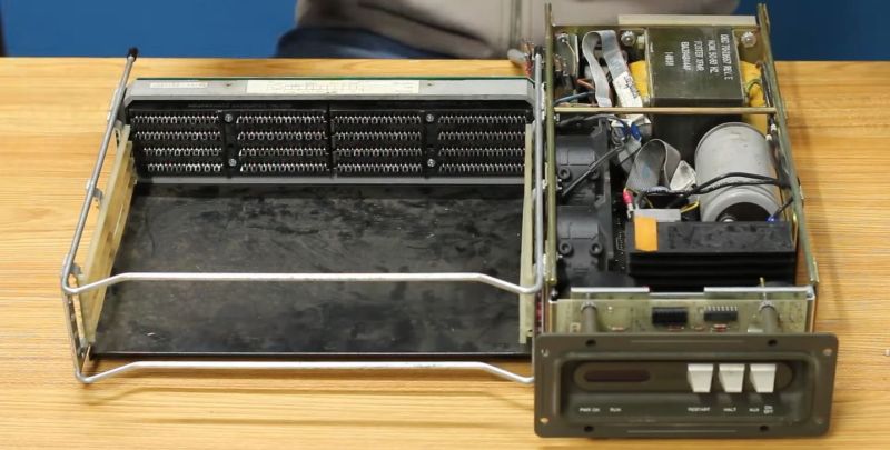
After [David Lovett] of [Usagi Electric] was donated a few cars full of DEC PDP-11 minicomputers of various flavors and vintages, he passed on most of them to loving homes, but kept a few of them himself. One goal of this being to put together a PDP-11 system that could be more easily taken to vintage computer shows than the ‘rollable’ PDP-11s he had access to prior. Of 1980s PDP-11s, the first-generation Large Scale Integration (LSI) PDP11/03 system (so-called Q-Bus models) is among the smallest, taking up about as much space as a 1980s desktop PC, while supporting the second generation LSI PDP-11/23 cards. It all seemed so easy until [David] tried testing the PDP-11/03’s PSU and everything went south.
Despite having access to the circuit diagrams of the PSU, figuring out what was going wrong was an absolute nightmare for [David], after some easy fixes involving replacing a blown fuse and bulging capacitors failed to deliver salvation. Reading through the comments to the video, it would seem that people are generally confused about whether this PSU is a linear, switching or some other configuration. What is clear is that with the absolutely massive transformer, it looks more like a linear power supply, but with a lot of protections against over current and other failure modes built-in, all of which rely on transistors and other components that could have gone bad.
Although in round 1 the PDP-11/03 PSU won the battle, we hope that once round 2 commences [David] will have had the proverbial training montage behind him (set to ‘Eye of the Usagi’, probably) and will manage to get this PSU working once more.


I think “Eye of the Rabbit” is more in line with Usagi.
B^)
I remember using 11/23 back in 79 or 80. Very sensitive to power surges. Had to install a huge external transformer to smooth out power to keep it from crashing.
I haven’t worked on that power supply, but ran into some from that time that had the linear regulator section replaced by a switching regulator.
Except that it’s not a linear regulator section. There was an application note for the 78xx series that showed how to use these in a switch-mode power supply, and this looks like approximately that circuit. However, I think his troubleshooting took a wrong turn: he removed the transistor that supplies current to the 7812, and yes, that turned off the 12V supply. But his conclusion that the transistor must be bad is probably not true. Removing the transistor just removed power from the 7812. The problem is more likely the 7812 itself, since THAT is what’s putting out excessive voltage, which the crowbar is then properly shorting to ground. Switch-mode power supplies are quite unforgiving.
It lools like two rails are a SMPS made of 6 transistors each. 5V 25A and same for -5V rail. Very high gain circuit, variable frequency. Ahhhh 1978.
My first paid job in electronics (in the late 80s) was working at a local company that had the representation of DEC. I was a technician in charge of repairing power supplies that other technicians would bring back from the field. Most jobs were easy, with the pass transistors damaged, occasionally some diodes or capacitors. I remember that crowbar circuit, all of the power supplies had them.
The configuration of a big iron-core transformer and a switching regulator was fairly common.
I remember one model (called the H777) where I had one or two non-working that I never could figure out what was wrong with those. I replaced almost every component, and still wouldn’t start. Older technicians used to joke that if 666 is the number of the devil, this power supply was even worse.
Without having the values of the resistors in the schematic, it is a bit difficult for me to understand how this works.
But seems to be something like this:
– When the power supply starts (or whenever the output is less than 5 V), the 7805 will conduct and will draw current from its input. Assuming the overcurrent circuit is not triggering, this current is supplied by R27, and the base of the driver transistor.
– This causes the driver transistor to turn on, which causes the pass transistor to turn on.
– This will cause the current through the inductor to raise linearly and the output voltage to increase.
– When the output voltage exceeds some threshold (close to 5V, but depending on the pot position), the 7805 will stop conducting (will try to power its output voltage by reducing its output current). This will cause the Control, Driver and Pass transistors to turn off, the free-wheeling diode will start conducting, and the energy stored in the magnetic field of the inductor will start flowing into the load.
– Eventually, the voltage at the output will drop below a value that will cause the 7805 to start conducting again and repeating the cycle.
For this to work, there must be some hysteresis in the circuit, and that is the part that I am not seeing. I think it may be through the resistor connecting the emitter of the pass transistor to the ground terminal at the 7805.
Keep in mind that the ground terminal of the 7805 is not connected to ground, but to a biasing network connected to a -15V power supply. The schematics show in the video do not show that -15V supply, but that is something else that should be checked. An old, open trimpot could also be causing problems there.
Just some armchair guesses…
This is exactly what I surmised when I analysed the circuit. There is hysteresis in there though, from the switching node on the inductor through a 20k pot (labelled freq adj) to the ground pin of the 7805. The voltage swing is divided right down to a few mV with a 1 ohm resistor connected to the voltage adjust pot. The bias can swing as low as -0.7V as there’s a diode there used as a voltage reference, pulled low with the -15V rail.
A mini version of the PDP-11/23, was the Heathkit H-11.
Had one, I regrettably sold it at a hamfest.
Wish I had kept it !!!
(still have a DEC VT05 CRT terminal though, need to
clean it up, probably get a good penny for it).
We used this QBUS 11/03 in the late 1970’s for embedded systems in rough factory environments. I noticed many for this exact power supply would fail with exploded capacitors. I called DEC’s LSI hotline and they asked for some of the failed power supplies. A months later they found the problem, they had used electrolytic capacitors in the AC side. They later fixed this.