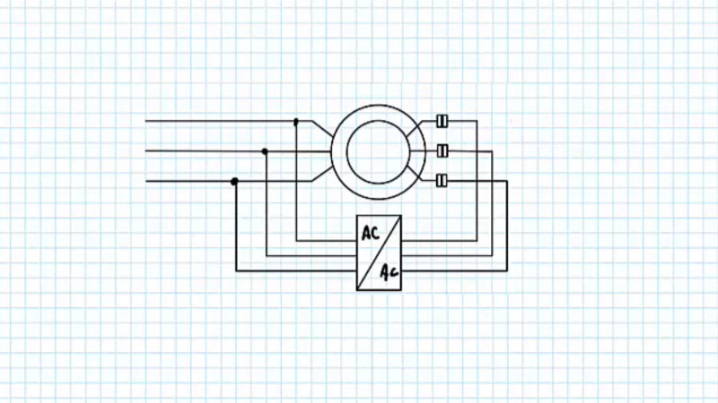
Somewhere in most engineering educations, there’s a class on induction motors. Students learn about shaded-pole motors, two-phase and three-phase motors, squirrel cage motors, and DC-excited motors. It’s a pre-requisite for then learning about motor controllers and so-called brushless DC motors. [Jim Pytel] takes this a step further in a series of videos, in which he introduces the doubly fed induction motor. If a conventional three-phase motor can have its coils in either rotor or stator, here’s a motor with both. The special tricks with this motor come in feeding both rotor and stator with separate frequencies, at which point their interactions have useful effects on the motor speed.
There are two videos, both of which we’ve put below the break. Understanding the complex interaction of the two sets of magnetic fields is enough to make anyone’s brain hurt, but the interesting part for us is that the motor can run faster than either of the two drive frequencies.
Sadly we’re not aware of any easily available motors using this configuration, so we don’t think it will be possible to easily experiment. But if you want to amaze your friends with an in-depth knowledge of motors, take a look at the videos below.


So what are the upsides and downsides? Is it more cost effective to repurpose an induction motor to be a synchronous motor?
They’re going out of fashion a bit because inverters have got cheap and commodity.
Back when a 1MW wind turbine was the gold standard, just about every turbine used a doubly-fed induction generator (which is the same as a doubly-fed induction motor, just run in reverse). They’re cheap and you only need a power converter capable of a fraction of the turbine’s output to synchronise it to the grid.
As turbines to bigger and power converters got cheaper, the advantages of a permanent magnet motor and a fully-rated converter became persuasive. Because the fully-rated converter can convert an arbitrary waveform to the grid waveform, you can apply torque through the generator in whatever pattern you like, which gives you a lot more options for control. It also helps you to extract more energy from the turbine, because it’s relatively straightforward to prove that aerodynamically the turbine is at its mos efficient at a higher speed and a lower torque in low wind conditions and a lower speed and higher torque in higher wind conditions. In a DFIG configuration, the torque provided by the turbine is proportional to the difference between the grid frequency and the generator terminal frequency (which is directly proportional to the turbine speed). There was some experimentation done with continuously-variable gearboxes but the complexity made them unreliable. Instead, being able to arbitrarily achieve a power through whatever combination of torque and speed you like (more or less) lets you operate at the aerodynamically-optimum point.
The DFIG configuration can also only provide significant torque over a relatively narrow speed range; the fully-rated converter / permanent magnet generator configuration allows you to apply significant torque at much lower speeds.
Thankyou Tom.
Permanent magnet generators aren’t a panacea, because the output voltage is proportional and fixed to the turbine speed, so pulling power out at low RPMs requires more current and causes greater I^2R losses in both the generator and the converter. The fact that they can operate down to lower speeds is a moot point, since the efficiency drops dramatically anyways, and the available power diminishes.
Wind turbines also don’t operate at a “lower speed and higher torque in higher wind conditions.” The turbine has an optimal tip speed ratio to the wind, which means at higher winds it also rotates faster to keep it in the turbine’s power band. If you turn the blades for a high torque low speed configuration, most of the wind just starts blowing right through the turbine without doing anything.
At lower wind speeds the turbine is likewise forced to turn slower – not faster. What you’re correct about is that there will be only a small fraction of the power available so you can’t load it up with very much torque. At the lower speed, the permanent magnet generator and the converter also operate less efficiently, so having this wider power band is a moot point. It’s actually a compromise to get rid of the fault-prone gearboxes rather than improving power generation.
Because of the physics of wind power, nobody’s really interested in what happens below wind speeds of 5-6 m/s. If the nominal power rating for the turbine is at 14 m/s, more than 95% of your total energy output will happen between 5 – 14 m/s. Going for the remaining 5% is not cost efficient.
Correction: power output. Energy output depends on distribution of wind speeds.
But even if your wind speed distribution shows an average under 5 m/s, that doesn’t mean you should have a turbine that can operate at low speeds – it means you’re building your wind turbine in the wrong place since it’s never going to make significant amounts of energy and you’re just wasting your money.
Dfigs are to problematic for wtg’s. I used to fix them. The added slip ring to the generator and an additional charging circuit just makes more trouble than it’s worth.
SFIG is the foundation of wind power generation.
Great explanation !
This is one of the best comments ever on the site, thank you for teaching me.
As with all brushed motors, applications are becoming increasingly limited. Their only modern applications are quite specialized and/or legacy.
This article is more of a history lesson. The future of electrical machines is in Brushless Synchronous (AC) Motors and Brushless DC Motors, paired with sophisticated power electronics.
Modern Inverters, VFDs, etc. can fit the niches that specialty motors like DFIGs were once only capable of.
I mean, many common corded power tools have brushed universal motors. They’re commonly found in stand mixers and sewing machines too. They’re super cheap for the power output and they have favorable torque-speed characteristics. A variac is better, but you can adjust their speed with a cheap AC chopper, or anything really, though you won’t get a fixed RPM under varying load without a brain involved. It’s hard to replace them except in devices that have to run on batteries.
The applications you describe are what I would consider specialty/legacy. These types of tools have incredibly low duty cycles and are typically discarded in the lifetime of their brushes. Automotive alternators are another example.
The exclusive reason brushed motors are used in the applications you describe is cost. Their use is analogous to the application of carburetors in small engines. If unit fuel injectors were a comparably economic option, they would 100% be used. It would be free efficiency/power.
Think of it this way; products are made to a price, so what these offer is often actually better performance for the same price rather than a cost reduction. The sort of things that I’d call specialty or legacy or even just plain useless are things like homopolar motors, or to an extent low voltage brushed DC motors, magnetos, etc. Or for the engines, something like making a hit and miss engine instead of one with a carb and throttle would be a better example of using legacy tech that doesn’t have a significant advantage.
There’s specialties all over the place.
For example, shaded pole motors haven’t gone away, even though they’re terrible in every respect. But, try designing a BLDC motor with a microcontroller inside a $50 microwave oven to turn the platter and see how far you get.
>to an extent low voltage brushed DC motors
Those still exist in the low wattage range because they’re easier to control on the electronics side, or when you don’t need any control at all and the MCU would cost extra. They’re also very robust against environmental variables like heat, cold, water, dirt… You could technically make small BLDC motors that commutate directly with Hall sensors like in computer fans without an MCU, but the Hall sensors and PCBs still cost extra, there’s more parts and they’re more complicated to assemble, and they require protective circuitry against bad electrical environments (e.g. car power systems) so the cost per unit is higher for no added benefit.
>magnetos
Those are commonly used for small wind turbines. The flat disc type with neodymium magnets rotating between coils is technically a magneto. An alternator that uses a permanent magnet for its magnetic field is called a magneto.
@Dude, the point is that the things I mentioned (low voltage brushed dc motors, magnetos) have a much narrower scope of applications, and better fit “specialty” or “legacy”.
And by magnetos, I mean like a small airplane has. Small engines use coils on the flywheel, most everything else new uses electronic ignition, without even a distributor generally. They’re still in small airplane engines because they’ve made the same engines for several decades and don’t plan to stop anytime soon. That’s a smaller niche than universal motors running on mains power, which are in all sorts of power tools plus sewing machines, kitchenware, and surely other stuff.
On topic (or maybe just slightly off) think of a classical rotary phase converter using a three phase motor which generates 3ph from a 1ph input.
One 1ph line goes into motor unchanged. But a branch from this one line in also goes into motor through a capacitor, thereby delaying current (and voltage) by 90degrees in that 2nd supply line. The motor then starts to rotate on 2ph – one of which is 90degrees from the other. When connected to a load, the motor output is 3ph separated 120degrees, with the third leg generated from the 3rd winding as the motor is spun by the incoming 2ph supply.
Question: how does the 90deg in get changed to 120degree out?
The capacitors don’t carry a lot of current, they’re just there to excite the field slightly, especially without a significant load (at a certain load, probably desired to be 100% and perfectly balanced, they don’t do anything at all). If they’re off thirty degrees it doesn’t matter. The vast majority of the energy is transferred inductively to the third terminal via the rotor.
Also, capacitors shift current through themselves by 90 degrees, but that doesn’t mean it’s enough energy to affect the voltage at the third terminal by 90. So 120 is measuring the voltage phase difference but 90 is current *through the capacitor* phase difference. Your downstream device only sees the voltage.
Excuse my lack of formal training in electronics, but it sounds like when a capacitor is being used in this manner that it is functionally a FIR Allpass phase shifter?
Aren’t these just a wound rotor motor? They were used in industry for variable speed applications where DC wasn’t available before the Variable Frequency AC Drives was developed. When I went to school we were told, these are old tech and you won’t see them in the field. The water utility that employed me after graduation had hundreds of them still in use. 20 years later they are still used in several facilities but control packages for some have been updated to solid state. Ours are all medium voltage (2300 and 4160). Line voltage is applied to the stator through a normal contactor, voltage to the rotor is controlled by a huge resistor bank with mechanical controls that are kind of terrifying to be near when switching. ( some are now solid state). Changes in rotor voltage results in changes to shaft speed which is great for controlling rate of flow with a centrifugal pump.
In re the wind turbine discussion; this 2016 piece may light some flames: https://www.cringely.com/2016/05/06/15262/
Ahem, this article seems to be full of bullshit!? Starts interesting and seems to be written quite well – but lacks any meaningful evidence whatsoever…
I worked in a furniture production facility in the 80’s. These wound-rotor motors were used extensively to make 3 phase at 240 hz by driving them externally with a normal 3 phase motor. This allowed wood carving machines to make base molding out of 2×6 lumber. They would connect a 2 pole 3 phase motor to the output of the rotor and run it at 4x normal speed. 14,000 rpm spinning blades-of-death. Still scares me to think of those chunks of metal flying off…
Gah. Electric machines were my least favourite part of university. Well, them and calculus.
For my sins, I’m helping rebuild a CNC machine at a maker-space. The spindle motor has a variable-frequency drive. This is something new to me, and maybe worthy of a HaD feature in the future.
Several years ago, I took apart an old Craftsman(?) Electric weed whacker, and it had a very similar motor in it. I was quite surprised by the elegant simplicity of it