If you need a potentiometer for a project, chances are pretty good that you’re not going to pick up a pencil and draw one. Then again, if you’re teaching someone how a variable resistor works, that old #2 might be just the thing.
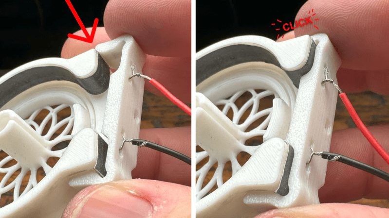
When [HackMakeMod] realized that the graphite in pencil lead is essentially the same thing as the carbon composition material inside most common pots, the idea for a DIY teaching potentiometer was born. The trick was to build something to securely hold the strip while making contact with the ends, as well as providing a way to wipe a third contact across its length. The magic of 3D printing provided the parts for the pot, with a body that holds a thin strip of pencil-smeared paper securely around its inner diameter. A shaft carries the wiper, which is just a small length of stripped hookup wire making contact with the paper strip. A clip holds everything firmly in place. The video below shows the build process and the results of testing, which were actually pretty good.
Of course, the construction used here isn’t meant for anything but demonstration purposes, but in that role, it performs really well. It’s good that [HackMakeMod] left the body open to inspection, so students can see how the position of the wiper correlates to resistance. It also makes it easy to slip new resistance materials in and out, perhaps using different lead grades to get different values.
Hats off to a clever build that should be sure to help STEM teachers engage their students. Next up on the lesson plan: a homebrew variable capacitor.
Thanks to [Keith Olson] for the tip.


Wow! This is such a interresting concept! I am wondering if there is some other resistive element with better longevity than paper… I’ve heard about people using old VHS tapes for DIY ribbon potentiometers, but it did not worked for me.
https://hackaday.com/2010/08/16/using-videotape-tape-as-a-controller/
Also shameless plug:
https://hackaday.com/2021/02/15/print-in-place-connectors-aim-to-make-wiring-easier/
A pencil ‘lead’ left in the pencil makes a fine linear resistive element for a linear pot: shave off the wood the expose the length of graphite. As long as you can tolerate the fairly low resistance: 20 ohms-ish. Curiously, mechanical pencil leads, despite much smaller diameter, are lower resistance than a typical ordinary pencil. Not great as a potentiometer because they are not very robust. But they make a nice glow-y hot element if put across a 12V battery, right before they briefly become an arc lamp.
O’ HaD, where’s the edit button?
You get the idea…
I imagine the resistance of 4H lead refills is going to be higher than 5B, and 0.2mm much higher than 2mm.
Speaking of the hot element, which works a bit better if you’ve got a constant-current supply, I’d like to try and get lime to stick to one of them and not flake off when heated. It’d take a lot longer to burn out if they weren’t literally burning away, and it’d be interesting to see if the lime would emit nicely like in a limelight.
The finer leads have more clay in them for mechanical stability, so higher resistance per area.
The softer the pencil, the lower the resistance.
The grades are what differentiates them on strength vs darkness. H for harder, with more clay or whatever, B for blacker with more carbon. The ones I was using said they used polymers instead of just clay, for better strength when using a 0.2mm or 0.5mm lead at a soft 2B or 4B.
Fine carbon powder and PVA glue or acrylic paint in a 50/50 mix makes resistive paste that can be squeezed in a mold and sanded down to adjust the resistance once it’s dry.
I made a level sensor for a plastic tank with 2 strips of aluminium tape stuck side by side on the outside which makes up a variable capacitor. This capacitor is used in a 555 oscillator and has enough resolution to measure a 25cm high tank.
^ That’s interesting I’d like to know more about that^
I once learned the hard way. Although the lead of a standard #2 pencil can in fact act as a resistor… it cannot handle much current at all! Done just right it might make a good heating element or firework starter though!
Cutting the paper straight verses tapered, creating a linear or a logarithmic pot.
I remember scraping some linear pots to customise the resistance profile.
I once used a carpenter’s pencil and a pritstick to make a multiturn linear variable resistor, pretty bulky but it worked quite well.
The best diy igniter I found has to be the metal wire inside sandwich bag twisty ties. Strip the plastic off and coil them around something thin. They get very hot, even with relatively low current draw.
Adding water to bluetac and wrapping it around one of the coils makes a dense ground hugging smoke. Perfect for wind tunnels.
Someone please make them fit for modularsynth controllers, those things are really expensive if you need lots of them.
There are a number of companies which produce resistive coated sheet film typically in rolls. The resistance specification is 0hms/sq (eg any square of the material, regardless of size, when measured from edge to edge will exhibit the same resistance) one such is https://www.caplinq.com/conductive-plastic-films.html
this is exactly how a variable resistor works, if anyone doesn’t like this they are arguing with science. we all know how that works out!
Actually – there are there are lots of other types of variable resistors like wire wound, ceramic, membrane, light dependent, etc.
That is exactly how one type of variable resistor works.
This is great timing. I’m going to try this with my son, because only yesterday i was teaching him to solder with a little project that involved a potentiometer. However, after following the links to source, I found the STL has the top and bottom pieces together in one object and I doubt it will print properly. My 3d editing capabilities are currently just tinkercad and I have no way of separating the top and bottom into a print. I would be very grateful if someone could post separate files for the top and base.
Is this really necessary? What benefit does it have over just showing them a potentiometer with it’s internals exposed?
I have seen a good number of potentiometers, usually cheap ones, that would be just as good at demonstrating the concept since they have no body covering them, you can clearly see the wiper and track. It probably wouldn’t be too hard to modify linear potentiometers to show this either. Or why not just use a wire wound variable resistor or rheostat to explain it?