When using a manual machine tool such as a lathe or milling machine, there can be a lot of pressure to read the position and feed the axes at the correct rate. That’s why modern machines typically have some form of digital read-out (DRO). [Stefano Bertelli] has created a simple Raspberry Pi based DRO with an additional twist, that of a linked motor drive output.
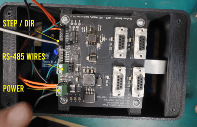
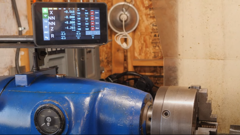
The axes that need to be monitored should be mechanically attached to a position sensor like a linear encoder or a rotary type. Using a linear sensor with a linear axis instead of a rotary encoder on the downstream dial is better. For the readout unit, [Stefano] used a WaveShare 7-inch touchscreen module with a Raspberry Pi 3 for the UI of the readout unit. The Pi has a custom-designed HAT, that performs power conditioning and provides a robust RS485 interface. Connected via that RS485 link is another custom PCB based on an STM32F411 with a few supporting power supplies and interfacing components. The job of this board is to interface to the position encoders, reading positioning pulses using interrupts. There is an additional stepper motor drive courtesy of a ULN2003 Darlington driver to allow the control of a single motorised axis. An additional motor driver module is required, which should be no surprise since driving a milling machine axis will require a fairly beefy motor. This GitHub repo contains the FreeRTOS-based firmware for this board. This motor drive has the ability to be connected to a measuring axis in a programmable way, enabling one axis to be adjusted to follow or jump in controlled steps with another. This feature can significantly simplify certain types of machining operations, as [Stefano] elaborates in the video.
Lastly, the Raspberry Pi runs a simple Python application with Kivy for the GUI. As [Stefano] explains in the video below, this makes debugging and modification quite simple.
Adding DROs to an older machine is an obvious but valuable hack. Here’s another way to do it. If that’s too much work, then you could just hack a digital readout calliper in there.
Thanks to [paulvdh] for the tip!


Wow! This is an impressive project. Thank you for sharing.
Only a single comment in two days? That is a bit unexpected.
If you look for example at this electronic lead screw article from a few years ago, it has 51 comments.
https://hackaday.com/2019/04/17/benchtop-lathe-gets-an-electronic-leadscrew-makeover/
and this can do all of that and more.
I am also interested in this project myself, but it is for a DIY machine that I still have to design and build, so that may take a while. I am also not sure yet whether I want to build this, (as an extra), or go full LinuxCNC, and integrate part of the functions of this into that setup.
Also, for the atrocious alignment of the rotary table, I am guessing that it’s not the engraving on the side, but that the worm wheel inside the thing is misaligned. I’d be curious to see a table plotted of the deviation taken every 10 degrees. If it’s the worm, then the deviation will be sort of sinusoidal. A really cool extension would to add a calibration table to this software. It would require a zeroing cycle to align the calibration table, but that is also doable.
Wouldn’t touchdro be a better and more accurate solution?
I realize this is almost a year later but I recently bought both the Touch DRO as well as this Dr.DRO version. Both are good but the TouchDRO works almost out of the box. This one is more “hey I wanna do cool stuff like link axis and make one control another”. It’s probably overkill for normie setups. Great if you want to control a rotary table and sync it with a hand wheel feed.