A raspberry pi-based digital readout above an old lathe

Roll Your Own DRO With An Added Twist

When using a manual machine tool such as a lathe or milling machine, there can be a lot of pressure to read the position and feed the axes at the correct rate. That’s why modern machines typically have some form of digital read-out (DRO). [Stefano Bertelli] has created a simple Raspberry Pi based DRO with an additional twist, that of a linked motor drive output.

A view of the custom RS485 interfaced DRO readout and motor controller
Realtime encoder position reading and motor control are best done with a dedicated microcontroller, ideally with a proper RTOS.

The axes that need to be monitored should be mechanically attached to a position sensor like a linear encoder or a rotary type. Using a linear sensor with a linear axis instead of a rotary encoder on the downstream dial is better. For the readout unit, [Stefano] used a WaveShare 7-inch touchscreen module with a Raspberry Pi 3 for the UI of the readout unit. The Pi has a custom-designed HAT, that performs power conditioning and provides a robust RS485 interface. Connected via that RS485 link is another custom PCB based on an STM32F411 with a few supporting power supplies and interfacing components. The job of this board is to interface to the position encoders, reading positioning pulses using interrupts. There is an additional stepper motor drive courtesy of a ULN2003 Darlington driver to allow the control of a single motorised axis. An additional motor driver module is required, which should be no surprise since driving a milling machine axis will require a fairly beefy motor. This GitHub repo contains the FreeRTOS-based firmware for this board. This motor drive has the ability to be connected to a measuring axis in a programmable way, enabling one axis to be adjusted to follow or jump in controlled steps with another. This feature can significantly simplify certain types of machining operations, as [Stefano] elaborates in the video.

Lastly, the Raspberry Pi runs a simple Python application with Kivy for the GUI. As [Stefano] explains in the video below, this makes debugging and modification quite simple.

Adding DROs to an older machine is an obvious but valuable hack. Here’s another way to do it. If that’s too much work, then you could just hack a digital readout calliper in there.

Continue reading “Roll Your Own DRO With An Added Twist”

See What You’re In For When Buying And Moving A Lathe

Sometimes, with patience and luck, one can score a sweet deal on machinery. But for tools that weigh many hundreds of pounds? Buying it is only the beginning of the story. [Ben Katz] recently got a lathe and shared a peek at what was involved in moving a small (but still roughly 800 pound) Clausing 4901 lathe into its new home and getting it operational.

The lathe had sat unused in a basement, but was ready for a new home.

Moving such a stout piece of equipment cannot simply be done by recruiting a few friends and remembering to lift with the legs. This kind of machinery cannot be moved and handled except with the help of other machines, so [Ben] and friends used an engine hoist with a heavy-duty dolly to get it out of the basement it was in, and into the bed of a pickup truck. Separating the lathe from its base helped, as did the fact that the basement had a ground-level egress door which meant no stairs needed to be involved.

One also has to consider the machine’s ultimate destination, because not all floors or locations can handle nearly a thousand pounds of lathe sitting on them. In [Ben]’s case, that also meant avoiding a section of floor with a maintenance trapdoor when moving the lathe into the house. Scouting and knowing these things ahead of time can be the difference between celebratory pizza and deep dish disaster. Pre-move preparation also includes ensuring everything can physically fit through the necessary doorways ahead of time; a task that, if ignored, will eventually explain itself.

With that all sorted out, [Ben] dives into cleaning things up, doing function checks, and in general getting the lathe up and running. He provides some fantastic photos and details of this process, including shots of the 70s-era documentation and part diagrams.

Watch the first chips fly in the short video embedded below. And should you be looking at getting a lathe of your own? Check out our very own buyer’s guide to lathe options.

Continue reading “See What You’re In For When Buying And Moving A Lathe”

(Re)designing The LumenPnP Tape Feeder

Many of the hardware orientated hackers among us will likely have been following along with the story of [Stephen Hawes] and the Lumen pick-and-place project but kind of waiting a bit for the project to mature some more before maybe taking the plunge and ordering a kit. One reason for this might be that whilst the basic machine design is there and working, the tape feeders did need a fair bit of work, and a lack of usable feeders does not make a great PnP machine. [Stephen] has been working on a newer design that addresses some of the identified shortcomings, and has started documenting his progress (video, embedded below) along the way.

Gone is the PCB-based ‘case’, reverting back to a 3D printable affair and a much smaller PCB. After flip-flopping a bit between different geared DC motors, [Stephen] settled back on the original, smaller unit, which after a wee spot of hacking, was convinced to accept an optical encoder stripped from another unit, and this proved that it was indeed more than up to the tape-advancement duty. The reason for this change was physical size — the original motor resulted in an assembly 38mm wide — this limited the number for feeders on the front rail to barely eleven units. This is not really enough, but with the narrower assembly, the width is reduced to 15.5mm allowing 27 feeders to snuggle together on the rail, and that should make the machine much more usable.

Continue reading “(Re)designing The LumenPnP Tape Feeder”

Angel Investor Gives Open Source PnP A Massive Boost

We love it when an Open Source hardware project grows up and turns into a sustainable business, bootstrapped with nothing but hard work and great ideas, but it’s a really tough prospect to do it using your own money, ploughing the profits from any sales back into development and not taking a dime in wages whilst you do so. People obviously need an income to live off, and that time spent working on a startup is time you can’t spend earning your keep. So it’s with great pleasure that we can bring you the latest news from [Stephen Hawes] and his pick-and-place machine plans. In the year since we last checked in with the project, development has continued at a steady pace, with the guys quickly outgrowing the garage workspace, whilst they prepare PnP machine kits ready for sale.

The big news is that [Joel Spolsky], co-founder of Stack Exchange, creator of Kanban management tool, Trello, and angel investor, has made a sizable ($100K USD) investment in the company which has allowed them to take on a 3,000+ sq. ft office space, and given them the funds for stock and all that boring business overhead stuff. [Stephen] takes time to explain that [Joel] will not have any control of the company, and all hardware and software will remain fully Open Source. For those interested [Joel] implemented his investment as a SAFE note (Simple Agreement for Future Equity) and as such, [Joel] will only make a return in the form of a small share allocation, if they hit the big-time in the future. Can’t really say fairer than that!

[Stephen] did recently receive a ‘cease and desist’ notice regarding his use of the ‘Index’ name for the project, since that is already a trademarked term, defended by somebody else, the project will need change name very soon. A minor setback, but it is a bit annoying that a chunk of that investment now has to go to a lawyer to make sure that the name they do eventually choose isn’t already taken and is safe to use.

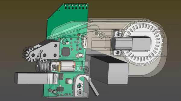
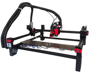
In terms of the machine itself, it is now is fully operating, with multiple automatic tape feeders, featuring up and down-facing machine vision, and all that OpenPnP goodness. It has even been demonstrated placing parts for its own custom motherboard PCB, reprap style. Nice!

We wish [Stephen] and partner [Lucian] all the success they deserve, and hope they get those kits out there, because there are people around these parts that need an affordable, hackable, desktop PnP machine ASAP, this scribe included!

Here’s the earlier story covering the machine, but it’s not the only Open Source PnP machine we’ve seen – here’s another one from a few years ago.

Continue reading “Angel Investor Gives Open Source PnP A Massive Boost”

Simple Plasma Cutter Collision Detection System

Machine tools often have powerful drive motors, allowing them to work quickly and accurately to get the job done fast. However, this can cause major damage if the tool head collides with an unexpected object. To protect against such occurances, [Xnaron] developed a simple system to shut down his plasma cutter in the event of a crash.

The system consists of a 3D printed collar that fits around the plasma cutting torch. The collar has two mating parts, which are held together with three magnets and three ball bearings to act as a key, maintaining the correct orientation. Three limit switches are then fitted, held closed by the two mating halves. When the torch collides with an object, this causes the magnetic coupling to seperate, triggering one or more of the limit switches, and shutting down the machine safely.

Video of an unplanned collision shows the device working well. It’s a neat solution that could probably be adapted to other types of machine tool that don’t experience high lateral forces. Of course, if you don’t yet have a plasma cutter, you can always make your own. Video after the break.

Continue reading “Simple Plasma Cutter Collision Detection System”

No Assembly Required For This Compliant Mechanism Dial Indicator

If you’ve ever had the good fortune — or, after a shop mishap, the misfortune — to see the insides of a dial indicator, you’ll know the workings of these shop essentials resemble nothing so much as those of a fine Swiss watch. The pinions, gears, and springs within transmit the slightest movement of the instrument’s plunger to a series of dials, making even the tiniest of differences easy to spot.

Not every useful dial indicator needs to have those mechanical guts, nor even a dial for that matter. This compliant mechanism 3D-printed dial-free indicator is perfect for a lot of simple tasks, including the bed leveling chores that [SunShine] designed it for. Rather than print a bunch of gears and assemble them, [SunShine] chose to print the plunger, a fine set of flexible linkage arms, and a long lever arm to act as a needle. The needle is attached to a flexible fulcrum, which is part of the barrel that houses the plunger. Slight movements of the plunger within the barrel push or pull on the needle, amplifying them into an easily read deflection. When attached to the head of a 3D-printer and scanned over the bed, it’s easy to see even the slightest variation in height and make the corresponding adjustments. Check it out in the video below.

We’re big fans of compliant mechanisms, seeing them in everything from robot arms and legs to thrust vectoring for an RC plane. This might look like something from a cereal box, and it certainly doesn’t have the lasting power of a Starrett or Mitutoyo, but then again it costs essentially nothing, and we like that too.

Continue reading “No Assembly Required For This Compliant Mechanism Dial Indicator”

Open Source Pick And Place Has A $450 BOM Cost

Give your grizzled and cramped hands a break from stuffing boards with surface mount components. This is the job of pick and place machine, and over the years these tools of the trade for Printed Circuit Board Assembly (PCBA) have gotten closer to reality for the home shop; with some models diving below the $10,000 mark. But if you’re not doing it professionally, those are still unobtanium.

The cost of this one, on the other hand, could be explained away as a project in itself. You’re not buying a $450 shop tool, you’re purchasing materials to chase the fever dream of building an open source pick and place machine. There are two major parts here, an X/Y/Z machine tool that can also rotate the vacuum-based parts picker, and the feeders that reel out components to be placed. All of this is working, but there’s still a long road to travel before it becomes a set and forget machine.

The rubber hits the road in two ways with pick and place machines: the feeders, and the optical placement. The feeders are where [Stephen Hawes] has done a ton of work, all shown in his video series that began back in January. The stackup of PCBs and 3D-prints hangs on the front rail of the gantry assembly, is adjustable for tape widths, and uses an interesting PCB encoder wheel and worm-gear for fine-tuning the feed. [Stephen’s] main controller board, a RAMPS shield for and Arduino Mega that runs a customized version of Marlin, can work with up to 32 of these feeders.

So far it doesn’t look like he’s tackled a vision system, although the Bill of Materials does include  “Downwards Camera”, confirming this is a planned feature. Vision is crucial in commercial offerings, with at least one downward camera for precise board positioning, and often an up-facing camera as well to ensure component position and orientation (if not multiple cameras for each purpose). Without these, the machine would be dead reckoning and that can lead to drift over the size of the board and the duration of the placement run as well as axial misalignment. Adding vision shouldn’t be a ground-up effort though, as [Stephen] chose to use OpenPnP to drive the machine and that project already has vision support. This will be much simpler to add when compared to the complexity of the feeders.

[Stephen] admits that much work still needs to be done and he would love to have help dialing in the performance of the feeder design, and fleshing out features on the road to perfection. Although we suspect that as in the early days of bootstrapping 3D printers, a project like this can never be truly finished. At least it’ll make his next run of LED glowties a lot easier to fabricate.

Continue reading “Open Source Pick And Place Has A $450 BOM Cost”