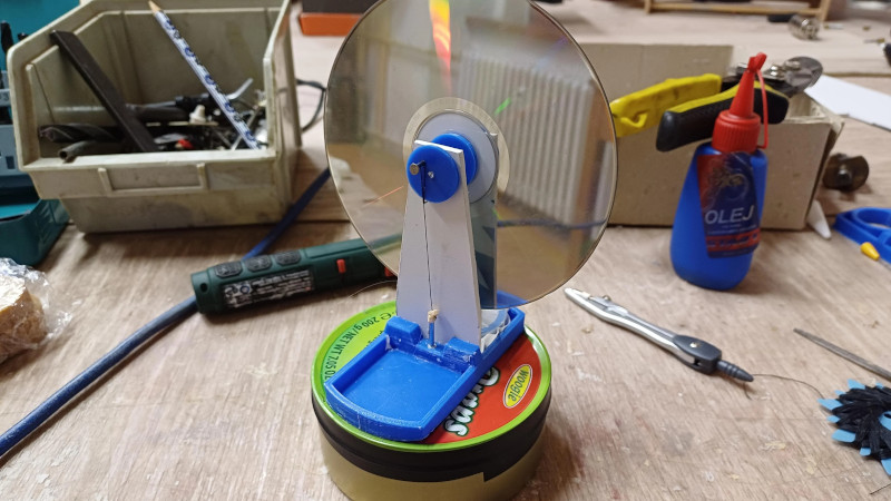
The model Stirling engine is a staple of novelty catalogues, and we daresay that were it not for their high price there might be more than one Hackaday reader or writer who might own one. All is not lost though, because [jirka.luftner] has posted one on Instructables which eschews the fancy machined brass of the commercial models and achieves the same result with an array of salvaged parts.
The main cylinder is a former apple drops tin with a cardboard displacer, and the CD/DVD flywheel is mounted on either a 3D printed or cut out frame with the secondary cylinder cut into it. A diaphragm for the secondary cylinder is taken from a rubber glove, and the cranks come courtesy of bent wire.
A slight mystery of this design is that it appears not to have a regenerator, or heat store. This usually lies in the path between the two cylinders to improve efficiency by taking the heat from the air as it passes in-between the two, and returning it when it goes the other way. We’re guessing that on an engine this small it’s the tin itself which performs this function. Either way this is a neat little engine that shouldn’t break the bank.
If this has whetted your appetite, you’ll be pleased to hear it’s not the first Stirling engine we’ve seen made from what was lying around.


This type of a stirling engine doesn’t really have a place to put the regenerator. You might integrate it into the displacer by adding small channels, but I’m not sure if it would work properly.
I have seen versions using steel wool but I don’t know if it was to make a heat stone or to make it heat resistant.
This style of stirling engine simply insulates the air in the tin from the hot bottom, or the cold lid, with a flap of cardboard. It doesn’t really use a regenerator at all.
The working volume is the entire tin. In other styles of the engine, the displacer would fill almost the entire volume to minimize the amount of air being expanded (less “dead” volume), so the expansion or contraction would happen mostly in the power cylinder. The air is pushed through the regenerator to quickly “pre”-cool or -heat it when it moves between the different chambers, minimizing the amount of heat that needs to be added or removed with each cycle.
The same style is possible here if the displacer is made thicker and the stroke shorter, so the air moves into a smaller volume under the lid. The regenerator would be placed around the displacer to intercept the air that flows up and down the sides of the tin. The walls of the tin kinda do the same thing, trapping or releasing heat from the air passing by.
Some model sterling engines use a ‘regenerative displacer’ by using a piece of foam instead of cardboard.
I wonder what sort of “voom” one might get using an 18″ diameter cake pan and suitably larger displacer and power piston/diaphragm. This Japanese college built engine of similar size produced 10 Watts.
http://www.bekkoame.ne.jp/~khirata/academic/kiriki/10wse/