Let’s face it — electronics are hard. Difficult concepts, tiny parts, inscrutable datasheets, and a hundred other factors make it easy to screw up in new and exciting ways. Sometimes the Magic Smoke is released, but more often things just don’t work even though they absolutely should, and no amount of banging your head on the bench seems to change things.
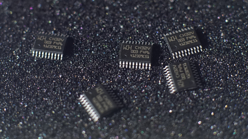
It’s at times like this that one questions their sanity, as [Gili Yankovitch] probably did when he discovered that not all CH32V003s are created equal. In an attempt to recreate the Linux-on-a-microcontroller project, [Gili] decided to go with the A4M6 variant of the dirt-cheap RISC-V microcontroller. This variant lives in a SOP16 package, which makes soldering a bit easier than either of the 20-pin versions, which come in either QFN or TSSOP packages.
Wisely checking the datasheet before proceeding, [Gili] was surprised and alarmed that the clock line for the SPI interface didn’t appear to be bonded out to a pin. Not believing his eyes, he turned to the ultimate source of truth and knowledge, where pretty much everyone came to the same conclusion: the vendor done screwed up.
Now, is this a bug, or is this a feature? Opinions will vary, of course. We assume that the company will claim it’s intentional to provide only two of the three pins needed to support a critical interface, while every end user who gets tripped up by this will certainly consider it a mistake. But forewarned is forearmed, as they say, and hats off to [Gili] for taking one for the team and letting the community know.


Both the 8 pin and the 16 pin variants lack the SPI functionality. This is right there in the second page of the datasheet–it used to be on the first page, but pagination pushed it to the second. Both of the 20 pin variants (QFN and TSSOP) have it and neither of the SOIC variants do.
It is roundly considered quite the oversight to not have it on the SOIC packages, but with 20 signals to start with, something has to give on the smaller packages. This isn’t some expensive chip with an I/O matrix. For every combined signal on a pin, that’s one more bond wire that has to be made for this $0.15 chip.
I’d also push back on the TSSOP20 being hard to solder. It’s quite easy to solder if you’ve done even a few SMD devices. I would suggest one avoid the QFN unless one really *likes* SMT soldering.
Can anyone get the discord link to work?
I agree, it is pretty common for some functions to be missing on smallest package variants.
In this case a workaround could be to use USART2 in synchronous mode, where it can be configured to work pretty much like SPI.
What I understand (I haven’t tried it in practice (yet)) from the STM datasheets is that on the very small packages they simply bond two pads to the same pin. So you’re supposed to program the other pad on that pin to “input” to prevent messing with whatever you want to do with the other pad bonded to that pin. That would’ve been easy to do. but then say SPI would’ve “broken UART2” or something like that. But you do have to have the bonding machine that can do that of course. Not sure if that’s an issue.
To clarify two pads to one pin: pads PA2 and PB4 might both be connected to pin1 of the package.
It doesn’t seem to be just bonding two pads to same pin.
For example STM32F042 has a bit in SYSCFG that “controls the mapping of either PA9/10 or PA11/12 pin
pair on small pin-count packages.” So the possibility of accidental short between two GPIO has been prevented in hardware.
If you really dislike the TSSOP20 you’d actually be better off *learning* how to do QFNs with a cheap hot air station. Surface tension isn’t enough to do all the work for you with TSSOPs since the packages are so much bigger, but with QFNs it’s basically automatic. Plus QFNs have the advantage that since they have no leads you basically can’t damage anything.
SOIC parts are trivial, with SSOPs the 0.635 mm’s are annoying, but once you get to the 0.5 mm pitch parts I’d much, much rather have the QFN than the part with pins.
Is another bond wire really required? I’d imagine it would be designed as a hardware mux. I’m not saying that’s free either, you still have to worry about supporting whatever drives, impedances, etc, are required for the different mux’d functionalities, and the die size, parasitics, and engineering hours that entails. It just seems like an extra bond wire would be the last way to do it, especially as you’d have to worry about the other considerations anyways.
Chips in different packages are often (very very often) the same die, just bonded out differently. You can’t add a hardware mux specific to one package, you’d need a new die.
I fall on the side of “they shouldn’t have called it MOSI/MISO then”: documentation-wise it’s easy to just define up a new ‘mode’ for unclocked synchronous serial in/out, name them that, and reserve MOSI/MISO/SCK for packages with all 3 signals bonded out.
Exactly.
It is not a CLK pin that is missing, it is simply a cheaper/smaller variant that doesn’t have any SPI functionality.
Having a “light” version of a chip which lacks certain functionality is actually very common.
They should have removed the MOSI & MISO labels on the pinout diagram, but other than that, it’s just they had to choose to lose something and SPI functionality was their choice.
Why would they want to remove those? Those pins still do have the MISO and MOSI functionality. If you want to stream out/in a bunch of bits over those pins, you certainly can. You just don’t get a clock signal to go with it.
This is useful for a lot of signal generation taskslike WS2812B LED driving. There’s an ‘abuse of SPI’ TX example in the ch32v003fun repo that uses SPI to drive a string of LEDs. You can use anything but the 8 pin part with that example. It doesn’t need the clock pin of the SPI to work, so it’s fine on the 16 pin variant.
So, in this case it seems the datasheet is correct, but the author should probably have put a line in cap letters saying that the clock is missing to help the unfortunate user. Generally, datasheets seem to ‘try’ to be unhelpful and dont flag such obvious pit falls.
I recently tried to locate a ‘missing’ hydraulic diverter valve on my robot tractor. The electrical schematic showed the presence of a switch and wiring, the mechanicals showed the actual mechanical lever, but the hydraulic schematic showed nothing. After 2 days of frantically deciphering hydraulic hieroglyphics and searching on the actual machine it was confirmed – NO DIVERTER VALVE. A quick phone call to a main dealer confirmed “Oh yeah, that manufacturer often leaves out features, presumably to keep costs down”. ….. At least I now have some idea of how the hydraulics work.
Another commenter pointed out that the lack of a clock line in certain packages is specified on the second page of the datasheet.
At the very beginning of the datasheet is a table with all chip variants and which features it has. You’ll see this version of the chip doesn’t have SPI functionality, so it is already very clear there should be no expectation of an SPI CLK pin.
MISO/MOSI can be used for other things than SPI.
However SPI requires MISO/MISO together with a CLK pin.
So, the chip doesn’t support SPI as already indicated in the capability table.
Why do people keep using slow discord?
It being unbrowsable is a fat bigger deal.
This. I absolutely refuse to use discord because it’s a black hole for information. Anything that points me to discord gets black listed.
If that was a design choice they should make it very clear. But I mean, can we ask anything from those people?
Do ‘people’ still write these datasheets or is it done by CrapGPT?
You mean like the chart on the second page of the data sheet that shows that the 8 and 16 pin variants don’t have full SPI functionality?
Why is this even a thing, as the first post here stats its not available and its on the datasheet. Why blame others for inept armchair engineers? When I really get into a chip I like, I read every freakin bit of the datasheet, I want to know that core inside and out. Sure we can abstract and use other peoples libs and be blind, but when you are a bare metal engineer and you are the one writing those libs (they dont write themselfs) you need to know the chip you are using. ok rant over.
So you use a smaller package and lose pins, who would have thought?
All that varies between manufacturers in that respect is how the lower pin count is managed. With these chips it seems they just don’t connect some pins but on others like the STM32 they do it differently allowing you to use any of the pins but they are connected internally, often leaving you with only being able to use one at a time.
TLDR: Author doesnt read datasheet, and gets upset when it doesn’t work like they assumed. Blames manufacturer.
Nothing to see here. Reading a datasheet is a skill, and the details matter.
Up next week: OP is cranky when BJTs blow up because theyre operated outside their SOA. “…but 5 Amps means 5 Amps!”
i don’t mean to disparage risc-v or cheap microcontrollers but as a hobbyist building one-offs, i am once again saying: rp2040! at n=1 i guarantee you won’t be able to detect the higher cost and it’s just amazing that they got to that low cost through a regular reputable supply chain without resorting to all the unknowns of areputational international drop shipping. the documentation and support aren’t perfect but it’s pretty good imo.
i just don’t understand all the competition at the bottom end of 32-bit microcontrollers when there’s such a totally okay offering on the market, a known quantity at a known low price point.
i’m really down on the broadcom raspberry pis — their low price point and relatively good support is a curse upon the landscape, enticing people to use entirely the wrong chip for their purposes. but the rp2040 is everything you want out of the lower-end stm or ch32 offerings, at a fantastic point on the predictability vs price curve.
RTFM :-)
In other news: dual version of opamp loses compensation pins (on purpose); discord crowd after not reading data sheets blames manufacturer.
“and no amount of banging your head on the bench seems to change things.”
There are electronic parts that seem to react to physical shocks, while not having been designed to do that.
And then there are the bad solder joints and tin whiskers and PCB cracks and loose connectors of course.
So banging your head is worth a try.
Why the hell is hackaday linking to some random discord channel? You might as well link to some file on your hard drive. file:///home/user/Documents/42.pdf anyone?