
Have you ever read about something and thought, “Gee whiz! Why did I never think about that?” That was my reaction to reading about a feature commonly associated with Klipper called adaptive bed leveling or adaptive mesh leveling. Too bad I don’t typically use Klipper, but it all worked out, and I’ll show you how it might work for you.
What Is It?
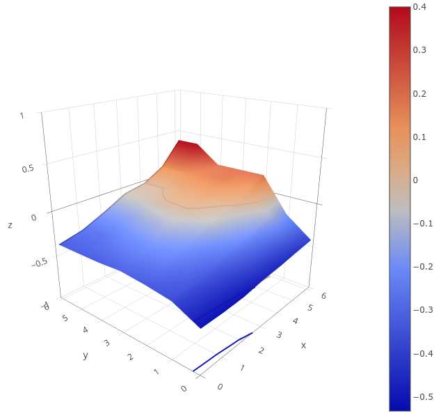
Once a luxury, most 3D printers now come with some kind of bed level sensor. The idea is that the printer can probe the bed to determine the shape of the build plate and then adjust the build plate accordingly. So if a particular spot on the bed is 0.5 mm too high, the nozzle can rise 0.5 mm when it is in that area. There are several techniques Marlin firmware uses, including what I usually use: UBL. Some people scan the bed once and hope it won’t change much. Others will do a time-consuming scan before each print.
However, adaptive bed leveling is a bit different. The idea is that the printer only probes the area where the part is going to print. If your print bed is 235 mm x 235 mm but your part is 50 mm square, you could just probe the points under the 50 mm square.
This does several things. For a given number of points, there is less motion, so it should be faster. Also, for the same number of points, you will have a much denser mesh and, thus, a better idea of what the bed is at any given point. You could even reduce the number of points based on the size of the part you are printing.
When you think about it, it is a dead simple idea. What’s not to love? For most print jobs, you’ll have less work for the printer, faster prints, and a denser mesh. But how do you do it?
How Do You Do It?
Can you make this work with your printer? Maybe. The trick is you need a way to tell your printer firmware to restrict the mesh area. You also need a way to have the slicer output a bounding box for the part, but that’s usually not hard. If you had to, you could even post process your Gcode and figure that out, but you probably won’t have to.
I
f you use linear or bilinear leveling, you are in business. That’s because the G29 command for bilinear accepts an L, R, F, and B parameter that lets you set the left, right, front, and back measurements of the probing grid. You can also set the number of probe points with H. Actually, H sets one side of the square, so if H=5, you will probe 25 points in the area.
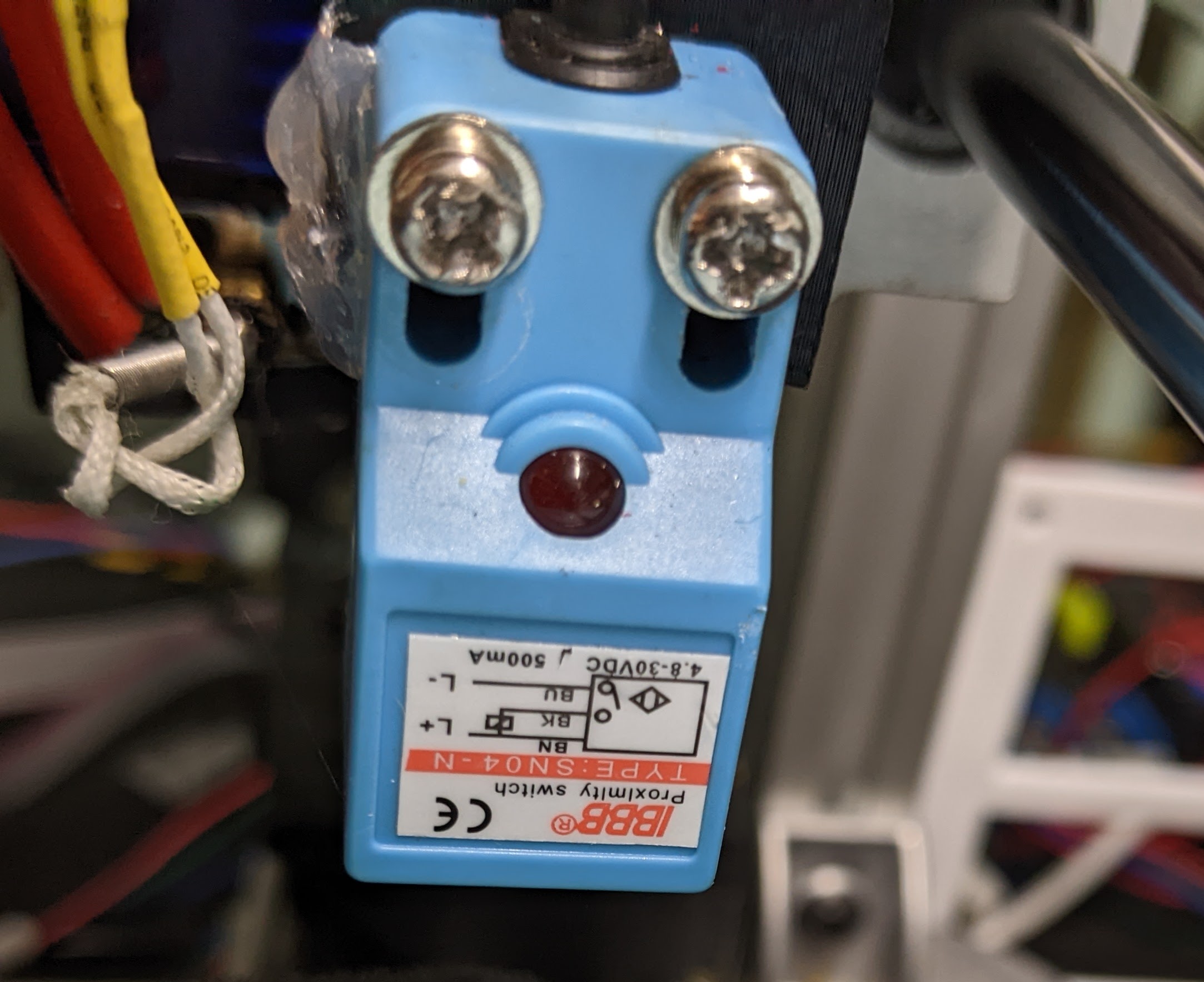
However, I use UBL, and on one of my printers, I think I’m out of luck without changing something in the firmware. While there is a mesh inset setting, it is set when you build the firmware, so it won’t be practical to change it on the fly.
However, two of my printers are Ender 3 v2 Neo machines. By themselves, they use some odd variant of normal leveling, but I long ago flashed them with the excellent “professional” firmware by [mriscoc]. This is Marlin configured for these machines and — at least the version I use — has UBL set. But, there’s a catch.
The firmware has some custom Gcodes that start with C. C29 sets the mesh size and location very much like other versions. For some reason, it also sets the temperature. Here’s the documentation:
C29 Ln Rn Fn Bn Tn Nn Xn Ym : set probing mesh inset (Left, Right, Front, Back) in mm. T is the probing temperature (T0 doesn’t change the current bed temperature) and N is the density or amount of grid points NxN, it is posible to set a NxM density by using X and Y. In UBL use G29 S# to save to a mesh slot number #.
Try It!
Just as an experiment, I sent the following to the printer via a terminal:
C29 L100 R150 F100 B150 T0 N5
Nothing happened. But when I performed a G29 P1 to probe the bed, it obeyed the new restriction. All that was left was to make the slicer output the correct startup code. Of course, if you are using bilinear levelling, you’ll use G29 instead and have to change a few of the arguments.
Engage Start Up Sequence
Most slicers allow you to put placeholder variables in your Gcode scripts. You may have to look it up for your slicer. There are also plugins that can do the work, but you’d need to change their G29 to C29 (in my case). I mostly use SuperSlicer, which is forked from PrusaSlicer, which is forked from Slic3r.
Here’s part of my startup code:
G28 ; home all
C29 L{first_layer_print_min[0]} R{min(190,first_layer_print_
That’s it. If you have a line that purges your nozzle, you might want to correct it using similar logic or just add a few skirt loops in the slicer and forget about it. Note that I probe 25 points, which might be a bit much for a small part. It would be nice to write a script to detect how big a part is and adjust things. Note that Prusa has enough power to do this totally in the start code, but it would be different in Slic3r or Cura. If you look around, there are a few different examples of doing this for both slicers and various firmware that you will — no doubt — have to adapt to your circumstances.
I need to crack into the firmware for my other printer to see if a similar C command is feasible to add. But that’s for another day, especially since the C29 command is provided as object code only, so I’ll have to start from scratch. Luckily, I’m used to building (and rebuilding) Marlin for all the machines, especially that one, since it is a custom blend of many parts. I may switch out to bilinear leveling. Or, I could break down and go to Klipper, I suppose.
We want to try fast scanning next. Of course, things are simple if you tram your flat bed once and forget it. That is until something changes.


After heating up, it takes more then 30minutes before a glass bed stops changing shape. Your fancy multi-point leveling isn’t as useful as you think it is.
Haven’t used a glass bed in years.
Bed levelling is very, very useful. Perhaps you’ll get better results if you let your glass bed rest hot for 30 mins?
Glass bed? What year is this?
PEI with PVP is the best thing ever. There are multiple types of PEI, from rough to smooth as glass. PVP is amazing on PEI. It works well on glass and other materials too, but on PEI it’s just epic. Your nozzle can just bump straight into the printed piece, no issues. I’ve bought a big (50mm) empty marker from Aliexpress. I put water in a sauce pan, add slices of PVP until it becomes a PVP liquid, then cool it off and fill the marker. The rest goes into a mason jar for later use. When I print something that can use the extra stability, I just use the marker on the bed and it creates a thin PVP layer that will glue the work down on the bed. It’s amazing. I never have warping issues.
Join the PVP gang, we got glue!
i’ve had issues with various materials sticking or releasing. also not having good ventilation in my particular situation makes me like glass. It’s just easier and my glass build plates were free. Picked up up off a coffee table someone threw in the trash. They are super flat and stay that way. really don’t warp at all. I also have adaptive bed leveling but i rarely have to use it with the glass beds. My other plates i had to re-run it every time. 30 minutes is nothing to wait for it to get to full heat compared to the pain of re-running the leveling after every single print. Honestly i have more issues on the other axis than i ever had with the z axis. This likely isn’t true for everyone’s setup. i happen to have a very nice and thick bed with a very large heater. heats up fast, stays even due to the thickness. honestly would be nice if i had better thermal interface between the bed and the build plate. Though I have not looked i’m not sure if anything like that exists as it would interfere with the flatness and be a pita to remove the build plate. so far seems to work fine though by just waiting, so i’m not complaining. Though I have a nice magnetic bed, the magnets lose strength as the bed gets hotter, so it’s almost a moot point once you hit a particular temp. With a rigid surface that cannot really warp there is no worry and i use clips to hold the bed in place, though I could likely print easily without using clips due to my setup not being a bedflinger.
All that to say i think a lot of the choices for build plates depends on the use case and the printer involved. My printer isn’t exactly one of those that is set up for a particular set of parameters and hardware, it’s more of a ‘chuck on anything you want’ kinda printer.
You mentioned mriscoc and tramming but completely failed to mention the tramming wizard. A lot of issues people have with their machines is that the bed is most likely twisted. Think of it as a flat plane between the 4 bed screws, if you measure those as reference points to each other, you can get a ’tilt’ map of the bed, in ubl you can use 3 points for this as an offset map to ‘fix’ your bed shape to a better looking mesh.
With a tramming wizard, instead of doing a 3 point tilt mesh, you do a 4 point quick mesh and then the firmware will tell you how much you physically need to adjust each bed adjustment knob so that all 4 points are aligned with each other and the probe tip, this will make your full on 5×5 or 9×9 mesh much more accurate and a lot easier for the mesh algorithm to work with it.
I have the professional firmware on my S1 and I wouldn’t go back to stock. Saying that the default Creality firmware sucks is an understatement. The tramming wizard is one of the handiest additions and makes levelling and tramming exceptionally easy.
The ‘professional firmware’ is crap. Try Klipper and you’ll see for yourself.
This is why the silicone mount mod exists for the Prusa MK3. The PCB bed and aluminum Y carriage are by default mounted with aluminum standoffs. Replacing those standoffs with silicone tubing lets you adjust the height at each point by turning the screw. The leveling plugin for Octoprint tells you how much to turn each one to fix any twist or warp in the bed at temp without having to mesh it out in software.
I am using one MK3S and one MK3S+ for years now (literally kilometers of filament) and haven’t even heard of this mod. I use the normal tight grid bed scanning with the PINDA probe before every print and never had any serious first layer problems…
Same here. Zero problems.
Or just use Klipper…
K.A.M.P. to save the day!
Just bringing my printer back to life after a minor disaster. Planning to install K.A.M.P. Once I’m back up and running. Can’t wait try it out!
KAMP is obsolete as Klipper supports adaptive meshing since some time. Just add adaptive=1 option to BED_MESH_CALIBRATE
https://www.klipper3d.org/Bed_Mesh.html#adaptive-meshes
If you want really fast meshing, you should use an eddy current probe like beacon and rapid scanning
The reason the temperature setting is in there is because some beds will warp as the temperature increases and the bed expands. Depends on how the bed is mounted, but if there are rigid connections between the bed and the frame then the bed expansion has to go somewhere. Best practice has always been to level the bed after it has come up to the desired temperature. (Unless you know you’ve designed your bed with a compliant mount to allow expansion.)
Exactly, temperature can change a lot of things. Even with a compliant mount it is still probably best to bring it up to temperature before probing.
Yes, I am aware of that and I actually have a 15 second idle built into my start code. However, with this setup, you specify the temperature, but it doesn’t seem to do anything. For this firmware C29 doesn’t actually do the probing. It just sets the inset and then you still do a G29 (and could set the temp if you wanted to). So my point wasn’t: why would you set bed temp for level? It was: why does this command need to know the bed temp?
I don’t know if there is considerable time-savings with adaptive mesh. The scan area is smaller, but a-movement and probing is the most time consuming… not moving between probe points.
BTW – you should just start using Klipper…
all the best recent innovations in 3D printing like auto bed leveling, input shaping, flow rate compensation hint at a single common philosophy for improving control and reliability in robotics software:
“ALWAYS ASSUME THAT THE ROBOT IS MISCALIBRATED!!!!”
the chance that the robot is ever perfectly XYZ aligned at exactly 90.0000 degrees, that flow rate of the cheap filament you got from amazon is the exact same as the fancy tuned branded PLA, that your belts are perfectly tight (but not too tight)… is PRACTICALLY ZERO, and if it is it’s a knock or a shake away from falling away from that perfect imaginary calibration.
by simply acknowledging this, adding sensors to measure the f**ked-uppedness and accounting for it in gcode you get reliable, it-just-works 3D printing.
I feel adaptive bed leveling as described might not add a huge amount to regular auto bed leveling to be perfectly honest. the beds are generally flat, rigid, well supported materials… but if this technique can shave 10-20 seconds off the time it takes to prep a print, then it’s a total win!
I am honestly so happy that my Bambu printer is just ‘print and play’, no tweaking required. As a maker I sometimes do miss the messing around with the older type of printers, making them print better and faster. But at the same time I can now just print and get my part printed out perfectly on the first try, so I can focus on the more fun parts of making stuff.
If you use the PEI beds they are not always flat. When I use glass, I do just do a 3 point level and done. FDM and CNC have superficial similarities but are very different for different reasons.
I tend to call this feature print bed compensation. What actually happens is the print bed deviations from the ideal are mapped and stored. There is no actual leveling.
Future prints benefit from the nozzle closely flowing the bed contour. This increases the first layer success rate because the extruded filament will bond properly and consistently.
It is a great feature, just poorly named, in my opinion.