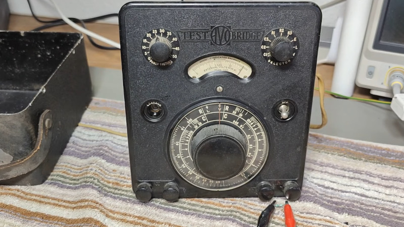
If you ever encounter a British engineer of a certain age, the chances are that even if they use a modern DMM they’ll have a big boxy multimeter in their possession. This is the famous Avo 8, in its day the analogue multimeter to have. Of course it wasn’t the only AVO product, and [Thomas Scherrer OZ2CPU] is here with another black box sporting an AVO logo. This one’s an AC bridge, one of a series of models manufactured from the 1930s through to the late 1940s, and he treats us to a teardown and restoration of it.
Most readers will probably be familiar with the operation of a DC Wheatstone Bridge in which two resistances can be compared, and an AC bridge is the same idea but using an AC source. A component under test is attached to one set of terminals while one with a known value is put on the other, and the device can then be adjusted for a minimum reading on its meter to achieve a state of balance. The amount by which it is adjusted can then be used as a measure of the difference between the two parts, and thus the value of an unknown part can be deduced.
In the case of this AVO the AC is the 50Hz (remembering that this is a British instrument) mains frequency, and the reading from the bridge is taken via a single tube amplifier to a rectifier circuit and the meter. Inside it’s a treasure trove of vintage parts with an electrolytic capacitor that looks as though it might not be original, with a selenium rectifier and a copper oxide signal diode in particular catching our eye. This last part is responsible for some reading anomalies, but after cleaning and lubricating all the switches and bringing up the voltage gently, he’s rewarded with a working bridge. You can see the whole story in the video below the break.
Test equipment from this era is huge, so perhaps not all of you have the space for something like this. Some of us have been known to own other AVO products though.


That “pigtail” of twisted wire might be a low value “gimmick” capacitor; maybe C8? See this: Gimmick capacitor – Wikipedia [https://en.wikipedia.org/wiki/Gimmick_capacitor]. A gimmick capacitor is a capacitor made by twisting two pieces of insulated wire together. The capacitance may be varied by loosening or tightening the winding. The capacitance can also be reduced by shortening the twisted pair by cutting. The available capacitance is on the order of 1pF/inch (0.4 pF/cm).[1]
1. “… twisted-pair wire makes an excellent variable capacitor, sometimes called a gimmick” Pease, Robert A. (1991). Troubleshooting Analog Circuits (1st ed.). Butterworth-Heinemann. p. 22. ISBN 0-7506-9184-0.
Troubleshooting Analog Circuits, Robert A. Pease. Newnes, 1991 – Technology & Engineering – 217 pages
https://books.google.com/books?vid=ISBN0750691840&newbks=0
I remember my high school Electronics teacher mentioning gimmick capacitors. But as I recall, they didn’t have to be a pair of twisted wires, an open ended PCB trace near a ground would also serve the purpose.