When we talk about audio amplifier tubes, we’re normally talking about the glass little blobby things you might find in a guitar amplifier. We’re not normally talking about big ol’ color CRTs, but apparently they can do the job too. That’s what [Termadnator] is here to show us.
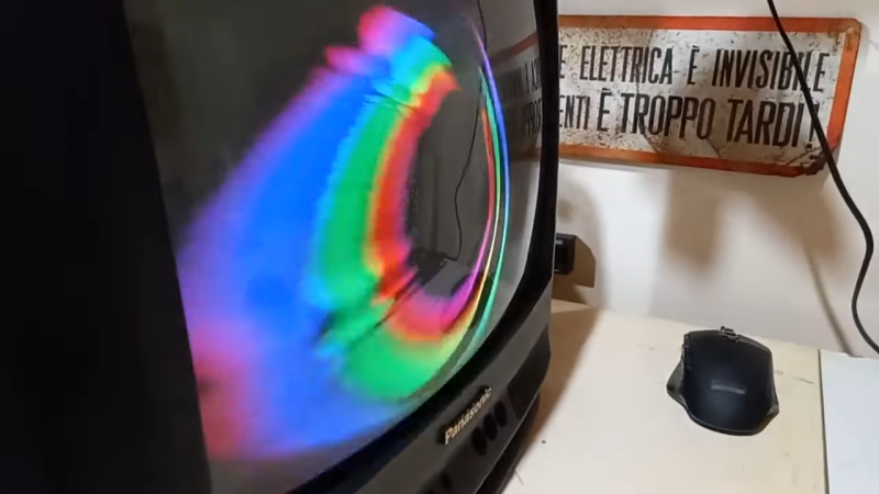
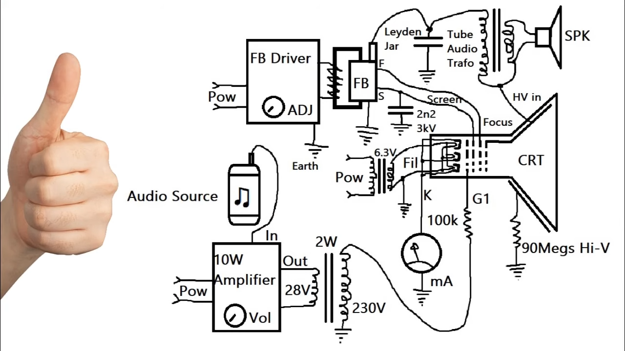 The CRT in question is a 14″ unit from a common garden variety Philips color TV. [Termadnator] pulled out the TV’s original circuitry, and replaced much of it with his own. He had to whip up a high-voltage power supply with a 555 and a laptop power supply, along with a bunch of fake MOSFETs pressed into service. He also had to build his own Leyden jar capacitor, too. The specifics of converting it to audio operation get a bit messy, but fear not—[Termadnator] explains the idea well, and also supplies a schematic. Perhaps the coolest thing, though, is the crazy color pattern that appears on the display when it’s working as an amp.
Sound output isn’t exactly loud, and it’s a little distorted, too. Still, it’s amusing to see an entire TV instead doing the job of a single amplifier tube. Video after the break.
[Thanks to bugminer for the tip!]


Now That’s a Hack!
For better audio quality and better impedamce matching on output side of CRT tube amplifer, I should use microwawe oven transformer or neon sign transformer.
Now that’s some proper hacking.
Thankfully they seem to be running at under 3kV anode voltage and not +20kV.
So less potential for suprize zaps and the HV PSU is a flyback and not a MOT, so less current available to bbq the experimenter.
I guess it could be made to make much more power with an output transformer that has a much higher turns ratio – pretty much the turns ratio of the flyback transformer would be needed here.
He has an input driver with 10W shouldn’t the output be more than 10W for the tube to qualify as an amplifier?
His speaker definitively does not output 10W.
But the color effects are cool. Analog winamp graphics!
Depends, I think. 10W aren’t always 10W.
There’s 10W sine (RMS?) and 10W PMPO, for example.
An amp with 10W sine outperforms a 10W PMPO amp.
Before the 90s or so, sine was normal, still. Cheaper, more modern amps use PMPO.
PMPO = Purely Mythical Power Out
I’ve even seen some amplifiers claiming higher output power than power usage! That isn’t even remotely believable…
The amplier cannot put out more power than it takes in – no amplifier can.
An amplifier merely puts out more power on the output signal than comes in from the input signal
I remember explaining to someone that CRT tubes are just very specialised valves, the socket on the back is just a valve connector.
Hurrah, proof!
Also, terrifying although I’m guessing this isn’t the full 20kV spicy setup.
I’m sure this would make an excellent wide-angle x-ray tube if the voltage is upped to 50kV or more!
Unfortunately(?) CRTs have special leaded shielding to prevent any stray X rays from escaping
> … wide-angle x-ray tube …
Not all hyphenated words pair well. E.g. Family-friendly Machine-gun.
What applications for wide-angle x-ray ?
It makes a dandy scanned-source x-ray source if you bump up the beam voltage.
Used to great advantage in certain medical imaging techniques, such as https://www.diagnosticimaging.com/view/cardiac-mariners-prepares-digital-x-ray-device-market
Also used for ultrafast computed tomography (Electron Beam Computed Tomography, EBCT), like the Imatron: https://ajronline.org/doi/full/10.2214/AJR.19.22681
Nice :-)
BTW: any electron tube that has at least one grid (i.e. is not a diode) can serve as an amplifier tube – even VFD displays can.
Obvious reference to and/or reminder of Korg+Noritake’s Nutube
Has anyone ever tried a stereo with a vfd display, where the vfd display was the amp for the stereo?
Eh, I’m not sure if any of my thyratrons would be great at “amplifying” much above mains frequencies. ;)
That visualization is the coolest side effect
The speaker needs to be in an enclosure to stop it sounding tinny and awful. The low frequency waves cancel out without a baffle.
I sort of believe the part that a CRT can be used as an amplifier. But how does the pretty visualization fill the screen without any deflection coils?
Did not watch the whole video, (I cant understand why everything today must be in video – have people lost their writing and reading skills?) but the parts I saw were mainly about the speaker.
He puts some magnets on a motor, so that the CRT doesn’t burn a spot.
Technically it’s a vacuum tube, but with a small bit of hydrogen gas and mercury, so a lossy one. Actual triodes and pentodes have a higher vacuum than a crt.
Use a zvs driver and you’ll be able to source higher currents and also change to the voltage output, make it louder and isolate the speaker and use impedance matching instead of common with the hv output, the audio will still make it through the transformer with isolated primary and secondaries
And clean up the signal with lc filters between speaker and secondary, like a band pass
I Don’t reccomend touching the speaker while using it with that schematic
Especially grounded
Even at 4kv
Probably might run better at 50kv 500ma
But problem with flybacks they need high frequency, so has to run over 30khz so you can’t hear the switching tones
Dogs and cats might scream bloody murder though
Can actually run it higher than the ~15khz
Don’t need to worry about the refresh rate
Not drawing a picture
But be careful of x-rays above 20kv
Crt usually lead lined to reduce but running it out of spec might want a Geiger counter around
With a CRT the anode so far away and undervolted, it’s not going to put out. Current will be miniscule. This is not rock’n roll. Better off to use a 6BK4 in an X-ray box. Or up the CRT voltage but then the output transformer has to take that, which takes you into Tesla Coil territory. Hmmm.
Well transformers can get really small above 20kv
It’s more of isolation of primary and secondaries
Could use another flyback for that purpose an ac flyback, or one with it’s internal output diodes removed, reverse fed and tap output from the smaller primary coils
You might be lucky, and that might work, but that’s not how flyback converter transformers really function.
An old flyback transformers that used a separate tripler, may be the go. Just use the transformer without the tripler.
I guess the problem will be the ferrite core that cannot pass any frequency under hundeds of hertz or even few kHz. Iron core transformer would be better, but if you use burner ignitor or neon transformer, remove those magnetic shunts for stronger power transfer.
By the 1980s, the tripler was molded inside the FBT housing.
Here’s a secret:
See if you can discover electron neutrino emission by magnetically phasing a 2 electron chain at a potential (same directional spin). Some electrons actually chain like this at the interstitial anode junction in the tube (pulled off the anode surface by passing electron) You’ll know you have phasing when the screen dims as the energy of the electrons is transfered to neutrino wavefunction.
Good luck!
Better off developing something you can run into a RF modulator that will make that funny colorful display so people can hook it up to the stereo system and watch the TVs that are all sitting around useless!
Good to see so many comfortable with vacuum tube technology. Was fixing 5 tube all american radios as a kid.
How about this? Some older radios, usually transformer powered had a tuning eye tube. If you can get a chassis, the power supply is there with a full wave rectifier. Somtimes the power supply choke doubled as the speaker magnet. Perhaps the eye can be reconfigured as an amplifier.
It is the most insane and amazing idea I have seen in years. But from the schematic it seems the speaker terminals are directly connected to the HV. No big deal just be careful.