The bottom of the sea is a mysterious and inaccessible place, and anything unfortunate enough to slip beneath the waves and into the briny depths might as well be on the Moon. But the bottom of the sea really isn’t all that far away. The average depth of the ocean is only about 3,600 meters, and even at its deepest, the bottom is only about 10 kilometers away, a distance almost anyone could walk in a couple of hours.
Of course, the problem is that the walk would be straight down into one of the most inhospitable environments our planet has to offer. Despite its harshness, that environment is home to hundreds of undersea cables, all of which are subject to wear and tear through accidents and natural causes. Fixing broken undersea cables quickly and efficiently is a highly specialized field, one that takes a lot of interesting engineering and some clever hacks to pull off.
A Series of Tubes
Understanding submarine cable repairs starts with understanding the cables themselves and the challenges they face once installed. Broadly speaking, undersea cables break down into two main types: power cables and data cables. While the number of undersea power cables is rapidly increasing, mainly thanks to offshore wind farms, their cable runs tend to be shorter and to stay within relatively shallow water. Data cables, which will be the main focus of this article, tend to be long-haul cables such as those that stitch continents together and face different challenges than undersea power cables.
There are currently close to a million miles of submarine data cable in operation, almost all of which is fiber optic. That’s pretty amazing considering that copper dominated the first 120 years of submarine voice and data cable construction, and that it was only in 1988 that the first transatlantic optical cable was laid. Optical networks have obvious benefits over copper coaxial cables in terms of data throughput and reliability of the physical plant; after all, copper and seawater don’t get along very well, and water always finds a way in. The trick with fiber optics is to find a way to safely handle the hair-thin glass strands and protect them against the conditions they’ll have to endure.
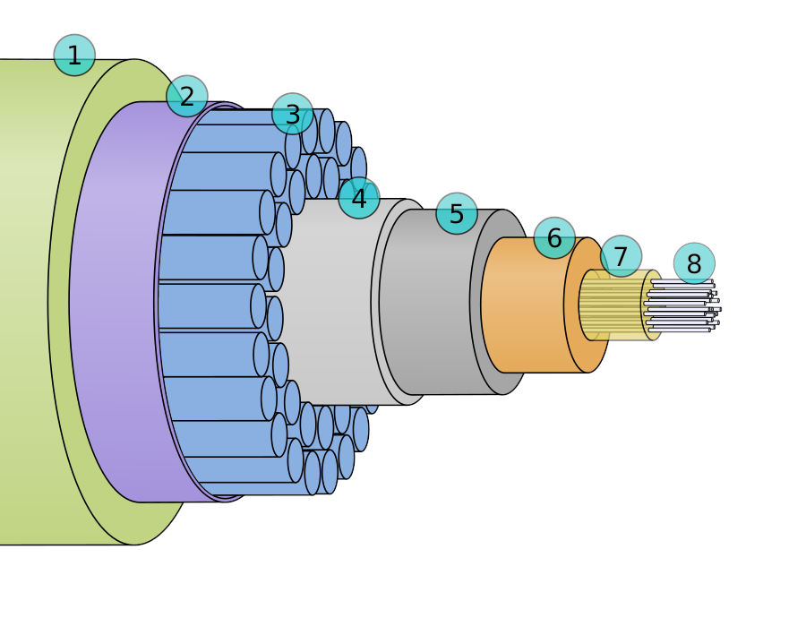
The core of a typical modern submarine cable will have multiple fiber pairs, often eight or more, with each fiber in a pair handling traffic in one direction. The fibers are bundled together in a tube made from either plastic, aluminum, or copper, with the space between the tube wall and the fibers filled with petroleum jelly or silicone gel to exclude air, which would compress at depth. This is wrapped in a polycarbonate or polyethylene jacket surrounded by a layer of galvanized steel wires wrapped in copper tape. The steel acts as armor for the fibers inside and provides mechanical strength, while the copper serves as a conductor for the high-voltage DC supplies at either end of the cable that power the inline optical repeaters that are spaced every 60 km or so. All of this is then wrapped in a thick polyethylene cover, completing the core of the cable.
Depending on the application, additional layers of armoring and protection can be added to the core. Cable destined for deep water installation with silty or sandy seafloor areas will often consist of the core alone. Cable installed in deep water but along a rockier bottom will usually get an extra wrapping of galvanized steel wires. Tougher bottom conditions and shallower water might require a cable with a double layer of armor wires or, for very challenging bottom conditions or in waters shallow enough that fishing activity or anchoring could present a hazard, a final outer armor layer may even be added. Armored cables generally have an abrasion-resistant outer wrapping of asphalt-impregnated nylon yarn.
The threat profile that a cable faces is very much dependent on depth. Close to shore, where human activity is the primary threat, installers often take the extra precaution of burying the cable. Where seabed conditions allow, cables can be buried as much as three meters deep in trenches that are dug by remotely operated plows straddling the cable and towed by the cable ship. Damage still occurs even with these precautions, with 70% or all cable casualties occurring in water less than 200 meters deep.
Once the water is deep enough to preclude anchoring, fishing, or sabotage — about a kilometer — the most likely source of damage is natural disasters such as underwater rockslides, seismic events, or volcanic activity. Even deep-sea currents are a hazard, as they can be powerful enough to move cables great distances and potentially drag them across rocks or wrecks. Whatever the cause, cable damage can range from scuffing or abrading the outer jacket enough for water to find a way inside, damaging a section of cable and gradually degrading performance to outright cleaving of the cable. It’s even possible for a long section of cable to be mysteriously removed in an apparently intentional act of sabotage.
Finding Fault
Whatever the ultimate failure mode might be, finding a fault in a cable that might be as long as the Earth’s circumference and could be 8,000 meters under the sea is no easy task. Cables typically come ashore multiple times along their length, and each landing has monitoring equipment to watch the vital signs of each segment. That isolates the fault to a specific segment of cable, but to dispatch a repair ship, the cable owner needs to pinpoint the fault as precisely as possible.
Spread-spectrum time-domain reflectometry (SS-TDR) is often used to locate and characterize a fault on active cables. Traditional time-domain reflectometry, which sends signals down a conductor to determine where any impedance discontinuities are by timing any reflections that come back from any impedance discontinuities along the way, can’t be used on in-use undersea cables thanks to the high voltages involved. SS-TDR, which was originally developed to detect faults in the wiring of airplanes using 400-Hz AC power, uses modulated pseudo-noise (PN) signals rather than a plain square wave pulse. The signals still bounce off any impedance changes introduced by damage, but an algorithm is used to correlate the returned PN codes with what was sent and when, making it easier to make measurements in a noisy environment. Optical TDR can also be used to locate fiber breaks, but since there are perhaps dozens of individual fibers inside a cable that would each have to be scanned, the fact that anything that would break one of them would likely breach the outer power conductor first makes it easier to just can that.
Once a fault is located, the cable has to be recovered. Very few cable repairs are executed on submerged cables; it’s just not the right place to open up a cable to work on it. While recovering something as small as a cable from perhaps thousands of meters below the surface seems daunting, knowing exactly where the cable was laid helps. That said, cables damaged by underwater rockslides or trawling accidents could be in a completely different spot than where they were laid, so locating the cable can be challenging. Also, some cable routes are packed with both in-service and obsolete cables; the transatlantic submarine corridor alone has dozens of cables that have to deal with the tricky topography of the Midatlantic Ridge.
While submersibles are sometimes used to identify the precise location of a cable, retrieving it is heavy work that requires heavy equipment. The cable ship travels to a point a couple of nautical miles away from the fault location and travels perpendicular to the path of the cable while dragging a cutting grapnel along the sea floor. The grapnel digs into the seabed until it snags the cable and begins lifting it. As the ship continues winching in the grapnel, the cable is forced against a cutting blade in the crotch of the grapnel, eventually severing it cleanly and completely. The cut ends fall back to the bottom where they await a second pass, this time using a special recovery grapnel. Once the first end of the cut cable is snagged, the ship’s crane winches it aboard so that a recovery buoy can be attached. This buoy marks the location of the first end, making it easier to recover later.
The Fix Is In
When both ends of the cable are hauled aboard, they make their way to the joint shop. This is an area adjacent to the “cable highway” on the ship, the cable-handling space located between the cable tanks amidship and the linear cable engine (LCE) that is used to pull cable out of the tanks and properly tension during deployment. The jointing shop has sturdy gear to secure the ends of the cable to the ship so that it doesn’t move during repairs; the cable ship also uses GPS-guided dynamic positioning thrusters to hold as precise a location as possible.
Cable technicians then get to work on repairs. If the damaged section of cable hasn’t been left on the seafloor it needs to be cut away, an arduous task for the more heavily-armored inshore cables. Once the outer jacketing and armor have been removed, the exposed fibers are ready for splicing. This is essentially the same operation as splicing terrestrial fiber optic cables; after the cladding is stripped off, the ends of the glass fiber are cleaved cleanly and positioned in the jaws of a fusion splicer. This device uses a microscope and machine vision system to precisely align the glass fibers in the gap between two tungsten electrodes before using an electric discharge to melt the fibers and fuse them together. The result is a physically and optically continuous low-loss bond.
When all the fibers have been spliced on both sides of the repair the cable is thoroughly tested. If the repairs are good, each splice is securely clamped within a joint body. This is a device engineered to both seal the spliced fibers and provide continuous mechanical support and electrical continuity. Once the joint is sealed and covered with multiple layers of polymeric waterproofing it’s ready to be returned to the seafloor. Lowering the cable is a delicate operation; you can’t just kick it over the side and hope for the best. The splice needs to be supported by a lowering yoke to reduce mechanical stress on the joint. The yoke is lowered on a cable equipped with an acoustic release hook which opens when it receives a specially coded ultrasound ping from the surface. The resulting bend in the cable is called a repair bight, which is carefully designed to respect the minimum bend radius of the cable.


All those metal components and high voltage power? No wonder sharks bite them…
Very interesting article!
I often dove the cable highway and explored the cable tanks of the Charles L. Brown, a cable laying ship that serves as an artificial reef after decommissioning. It’s an impressive ship, even submerged.
https://atlantic-cable.com/Cableships/CharlesLBrown/index.htm
I recommend you disconnect immediately
I see what you did there with “a series of tubes”
Where’s the return for the high-voltage?
an insightful article – lately we have been having slow Internet in our country and the most recent reason given is that a fiberoptic cable is damaged and being repaired, which has taken 2 months and may take 2 more – is there some place where the ststaus / health / bandwidth / power type related data is shown for the vast network of undersea cables ?
Do the companies that own and run them share such data ? similar to the NASA Deep Space Network site ?