We don’t know how you feel when designing hardware, but we get uncomfortable at the extremes. High voltage or current, low noise figures, or extreme frequencies make us nervous. [Orion Serup] from CrabLabs has been turning up a few of those variables and has created a fairly beefy 3-phase motor driver using GaN technology that can operate up to 80V at 70A. GaN semiconductors are a newer technology that enables greater power handling in smaller packages than seems possible, thanks to high electron mobility and thermal conductivity in the material compared to silicon.
The KiCAD schematic shows a typical high-power driver configuration, broken down into a gate pre-driver, the driver itself, and the following current and voltage sense sub-circuits. As is typical with high-power drivers, these operate in a half-bridge configuration with identical N-channel GaN transistors (specifically part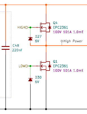 EPC2361) driven by dedicated gate drivers (that’s the pre-driver bit) to feed enough current into the device to enable it to switch quickly and reliably.
The design uses the LM1025 low-side driver chip for this task, as you’d be hard-pushed to drive a GaN transistor with discrete components! You may be surprised that the half-bridge driver uses a pair of N-channel devices, not a symmetric P and N arrangement, as you might use to drive a low-power DC motor. This is simply because, at these power levels, P-channel devices are a rarity.
Why are P-channel devices rare? N-channel devices utilise electrons as the majority charge carrier, but P-channel devices utilise holes, and the mobility of holes in GaN is very low compared to that of electrons, resulting in much worse ON-resistance in a P-channel and, as a consequence, limited performance. That’s why you rarely see P-channel devices in a circuit like this.
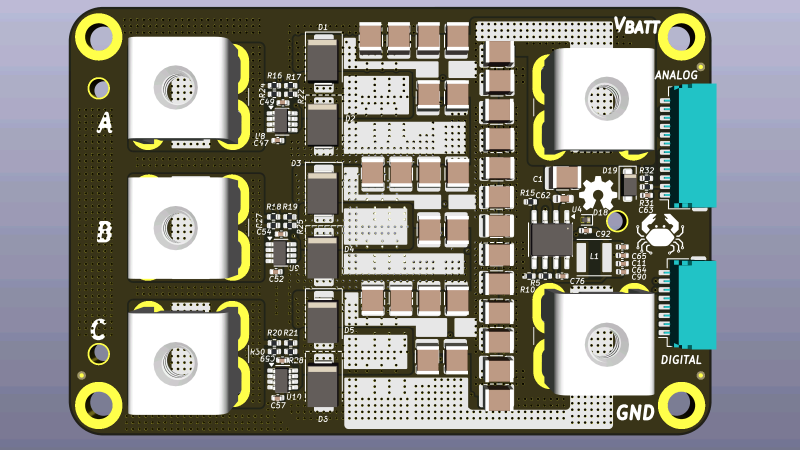
Of course, schematic details are only part of the problem. High-power design at the PCB level also requires careful consideration. As seen from the project images, this involves heavy, thick copper traces on two or more heavily via-stitched layers to maximise copper volume and lower resistance as far as possible. But, you can overdo this and end up with too much inductance in critical areas, quickly killing many high-power devices. Another vital area is the footprint design for the GaN device and how it connects to the rest of the circuit. Get this wrong or mess up the soldering, and you can quickly end up with a much worse performance!
We’ve seen DIY high-power controllers here a few times. Here’s an EV controller that uses discrete power modules. Another design we saw a few years ago drives IGBTs for a power output of 90kW.


I never looked into GaN semiconductors, so I’m a bit confused. I was trying to find some beefy transistors on the rendered images to no avail. Are those tiny blue blobs actual transistors handling 70A of constant current? In a 3 by 5 millimeters package?
A clue might be to follow the heavily stitched PCB traces and see what components they link to.
Amazing
even a D2PAK is way bigger then the actual device inside
also GaN is no longer magic smoke, but pure unicorn farts
D2PAK: I would have thought it was the name of some rapper if I had seen on any other forum.
Yup. GaNFETs really are that tiny.
Indeed, the GaN transistors are in 3x5mm packages. These are big transistors. Don’t let garden variety TO-92 packages fool you, the transistor dies inside those are tiny by comparison. Check out the EPC2361 datasheet. I has beautifully detailed drawings showing how to sandwich these between the PCB and heatsink.
It’s available in SMD package as well as in extended legs transistor outline. Gallium-Nitride (GaN) Enhancement Transistor EPC2326 as seen in this article is an SMD device of 3x5mm rectangular package. This device can handle 101A Constant Drain current while the Max Drain to source voltage is 100V DC.
LOCATION of Devices in picture:
Have a look at the extreme left of the picture, where 3 output terminals marked A B C. Towards right one can see 6 Black Rectangular blocks arranged in a vertically aligned line. These are the High power Semiconductor device. A pair is used for each phase to drive a e phase Motor
is there really any big advantage to using GaN for a motor driver? it not like that needs MHz switching speed
With GaN, you can go with dead time to ns range. Which means lower audible noise, lower torque ripple, better efficiency etc.
also lower Rdon, so less cooling needed
Rdon for the ones in the article is 1mOhm, regular mosfets will do that
@5V gate voltage and full drain current? Also does much better when things get warmer…
According to the github page, max power is 4KW. Three phase power is strange…
Looks like magic to me.
Datasheet:
https://www.epc-co.com/epc/Portals/0/epc/documents/datasheets/EPC2361_datasheet.pdf
And for magic it’s quite cheap. Only USD 8 per piece, or USD5 for 1000+
https://www.digikey.com/en/products/detail/epc/EPC2361ENGRT/22170707
It also takes hierarchical schematic design in KiCad to the extreme. A bit too far for my liking.
I like schematic sheet reuse, even if it adds a bit of complexity, because it ensures that all three half bridges of a circuit like this are the same, even after making revisions. You just modify one circuit.
The reason I do not like it, is because it takes quite a lot of time to navigate though the hierarchy. Each page is a zoomed in small detail with just one IC on it. It makes it difficult to discover that the way the grate drivers are just connected in the normal way to the FET’s. I would have preferred to have both a gate driver and the power FET’s on the same sheet.
There are also an awful lot of capacitors on this little board. Both understandable and good, but they take up so much space on schematic sheets, there is little room left for an A4 sized sheet for much else. I think the schematic would be easier to read if these capacitor banks were moved to their own sheet(s), so the other sheets have more room for actual active electronics.
Next, Routing power and GND though the hierarchy with quite a lot of hierarchical labels is quite confusing. For example, I had to use the highlight function on the PCB, to verify that the input power (VBATT) is actually directly connected to the high side MOSfets. On the PCB it is just a short fat track (as it should be in a project like this) but this net gets renamed multiple times through the hierarchy.
Some other small details: U4 (LM5164) has a direct link to the Ti datasheet, but the MOSfet’s don’t. Datasheet link to the LM1205 is not functional. Overall I do not trust links to some random place on the ‘net much. Once I’m halfway a project, I usually put all the related datasheets inside the project tree, and update the schematic to use the local copies. But this is a personal preference.
Does this project require additional heat sinking? (Maybe a thermal pad to a bigger heatsink?
How well is it tested?
But overall, it’s an amazing project. I also like the crablabs logo.
Some more notes about the PCB layout.
Layout of Vbatt is not optimal. It necks down to just 4mm on the “north” side of the PCB, and this detour around all the GND for all the row of capacitors also lengthens this track. Making this track shorter and wider (i.e. no routing to the north side). is better.
Copper is specified as just 35um for all 6 layers. In PCB’s like this it’s relatively common to use thicker inner layers (for more copper) and thinner outer layers (for higher etching resolution) and placement of the small SMT stuff and signal tracks.
There are a gazillion amount of via’s here, but what do they do if copper geometry is just (almost) copied to all layers. A much better approach would be to dedicate some layers to a full GND zone, and other layer(s) to a full Vbat distribution on the west side and connection to motor terminals on the east side. Full GND plane is also better for EMC, and maybe for the switching of these fast FET’s.
Putting all those vias under all the high current terminals is useless. These terminals themselves already have 4 thick prongs right through the PCB. The via’s add nothing.
It’s better to rotate the high current terminals 90 degrees. This balances their resistance / impedance because it’s more symmetrical. This also places the prongs of the high current terminals symmetrical to the shunt resistors.
With 0.5mOhm the shunt resistors are probably metal, and sturdy. PCB’s with big terminals such as this receive quite a lot of mechanical stress during mounting of the cables. This can easily break brittle ceramic SMT parts. Putting the mounting holes far away in the corners makes this problem bigger. For motor drivers such as this, I prefer either THT pads or SMT pads with vias for mechanical strength so the copper does not get ripped of the PCB and then directly solder wires to the PCB. This is a common technique for ESC like BLDC motordrivers. Soldering is a bit of a nuisance on a heavy copper PCB, but it’s also more compact (shorter tracks) and there is much less mechanical stress from things such as screwdrivers.
It’s just a few thoughts, do with them as you wish.
They definitely had some spare vias laying around …
Caveat – this seems to be a 4-layer board, but it is impossible to actually tell without the Kicad PCB layout files. At least the current sense traces are neither on the top nor bottom layer. Though, the massive amount of vias allows to tell something about the routing of the inner layers.
The vertical row of capacitors IMHO is mostly pointless. When you draw a loop to the nearest half-bridge, you can see that either the VBat connection is long, or the GND connection is long.
Fully agree with the remarks regarding the narrow VBat trace, thats just bad.
Recommendations:
– Dedicate the connector (“Bottom”) side to VBat, and the other side to GND
– Remove the capacitors 1/5/9/13 (counted from the top) from the capacitor row, add a horizontal VBat trace in their places on “Bottom”. Feed the cacitor GND using vias from the “Front” layer.
– Break the long vertical VBat trace on “Front”, add horizontal GND traces. Just keep the horizontal traces to the smaller capacitors.
– Remove the vias between the small capacitors and the GaN switches, keep the capacitors as close as possible to the switches.
– Remove all the pointless vias. Just keep the ones where the current is actually jumping layers. Most of the vias are in the way of the current, making the effective width of the traces narrower.
Some of these recommendations may be already taken care of due to the invisible inner layers.
Definitely 6 layers. The article above has a direct link to github KiCad project, with CERN Open Hardware Licence Version 2 I could not have made half the remarks I did without studying the schematic and PCB layouts.
This is textbook feedback. Informed, insightful, non-judgemental, and positive. If I had designed this board I would be delighted to receive it.
For covering 90kW, it requirs 6X3 GaNs required ?
Are the INA shunt amplifiers properly ‘kelvin’ connected? I can’t see this in the design, I’m not that good with KiCad yet. In the past we have seen some dV/dt sensitivity on this part (seen on TI’s 3PhGaNInv board), so we modified sampling timing to avoid the switching events.
It’s nice to see phase voltage measurements for sensorless control becoming more and more popular. The filter pole is not what I would expect, something in the 300-500 Hz would be more convenient for me. Instead of the STM32F405 I would use an STM32G4 series MCU, as it will support the ST HSO/ZeST algorithm.
They are kelvin connected on the back and I switched to INA241 due to similar issues, seems better
Original Author here
Thanks for the feedback. I agree with most of the points. The design posted is the first version that worked more or less and thus is definitely not perfect.
The project started as a very cheap motor controller, thus vias are used to basically beef up traces on boards with thin copper foil layers, this is no longer the case so I will be removing them.
The later version basically implements the changes: we went to 3 oz inner layers (may up to 4 or more later), we more or less dropped routing power on the outer layers except for some small exceptions. We have solid GROUND and POWER planes internally, connectors are rotated in orientation (this also optimizes air flow in our case), we are keeping the connectors as they are pretty much a requirement.
The final configuration is a sandwich with thermal interface (and heatsink etc) on the FET side and minor thermal management and covering on the other side. Thus far we haven’t had any issues with components breaking or anything like that but we may take your advice in the future.
It’s still a remarkable project but I found yet again an unusual layout detail.
These FET’s have interleaved multiple source and drain pads, but on the PCB these pads are mostly connected on one side, and they form thin bottlenecks with a high current density, and that is not optimal. By using the internal planes more creatively (instead of stacking the same copper layout on multiple layers) as I mentioned earlier, it is also easy to break out these pads on both sides. The datasheet does recommend to connect these terminals in this way.
Gate / source voltage of these FET’s is extremely low. threshold is just 1V and a maximum of only 6V. That puts some extra limit on allowable parasitic parameters.
Earlier I did not know about extra heatsinking. The datasheet has a page on this, with a recommendation of a thermal pad and a heatsink on top of these FET’s. It also links to a application note with further details.
Capacitances in this FET does not look like it’s exceptionally low.
Overall, I’m getting serious doubts whether this FET would be a good choice for a motor driver. For a motor, there is no need for extreme fast switching, because PWM frequency can be relatively low, and fast switching makes EMC problems bigger. The datasheet does mention motor controllers (Only up to 60V!) It is easier to understand to use this FET in SMPS modules, where higher PWM frequency directly translates into smaller inductor size and better control of output voltage and current.
So the big push for GAN in motor drivers was new switching methodologies. If you are just doing a standard trapezoidal drive, there are better FETs out there.
Where GAN shines is FOC or FEC. With those switching methodologies you are switching at MUCH higher frequencies and spend much more time in the transition period (where most FETs generate the majority of their heat losses). All of a sudden GAN and it’s faster switching times looks a lot more lucrative.
I dunno, I once ran a 40Kw motor with 5KHz swiching to over 1000Hz AC phase current using FoC. Pretty deep into field weakening too. I had to run the control every 1/2 PWM cycle, and have an algorithm that stays stable and performant in the face of many non-idealities.
Reducing switching time too much leads to higher radiated emissions. It’s a trade between that or heating with longer switching time.
Thanks for mentioning FEC (Field Estimated Control), I did not know of this control method yet. It seems almost impossible to me to control a motor with no phase current/voltage sensing at all, instead relying only on an encoder (and a mathematical model). Guess I have some learning to do.
Fixed all of those issues in the latest changes. Thanks for the feedback.
This is mainly a hobby project but the main reasons why we went for GaN are as follows:
The power density is much higher, so for things like electric bikes it makes sense.
The higher switching speed leads to more efficiency in the system as a whole (you can get up to 10% better system efficiency in our tests)
Higher frequency switching means you can pretty much drop all electrolytic Caps which increases reliability and reduces size even further (see point one)
Way less switching losses
No reverse recovery charge (further increases efficiency and actually reduces EMI in some instances)
Essentially zero dead-time (reduces noise and increases efficiency)
The switching speeds we are targeting are in the low 100s of KHz, comparable SiC or Si chips very much struggle to get anywhere past 50kHz and switching losses become crazy.
Guy who designed it here: thanks for the feedback.
I will be taking a decent amount of the advice here. I agree on the capacitor sheet especially, it got a little more cluttered than I liked. I will be baking the datasheets into the project and using local links. We have an internal policy of no global labels (with some exceptions) but I will be reducing the naming issues with the high voltage power.
This project requires heatsinking above like 1500W or so at 25C. We are still working on making/buying a suitable heatsink that meets all of the requirements, but we have some internal prototypes that work as far as we have pushed them.
Thermal conductivity in GaN is not better than Si; it’s just that the loss of thermal conductivity does not become a detriment because the heat load reduction is so high.
I’m not well versed in motor driver design, but I REALLY appreciate the in depth analysis of this design by the readers here. This sort of constructive analysis really makes Hackaday shine. Thank you !
Pure MLCC DC bus decoupling without damping, and with different values in parallel seems like a recipe for resonances in the PDN, especially when paired with wiring inductance on the supply side. Some damping in the form of electrolytic capacitors and/or RC snubbers would be strongly recommended. Also the highly non-linear capacitance of class II dielectrics and the low ESR of MLCCs can lead to huge DC bus overshoot if/when hot-plugged. I’ve observed 130 V peaks when hot plugging designs with MLCC decoupling to a 32 V supply. Some sort of inrush management is mandatory, or at least heavy clamping and damping. With only 20 V voltage overhead between the device maximum Vds rating and the operating voltage, this will be challenging.
I agree and see where you are coming from. I will definitely be adding an RCD snubber between the power and ground. Thus far it hasn’t been a huge issue in terms of overshoot or ringing but we have yet to push it on the high end of the voltage range.
OK, I’m going to show my ignorance. If it is limited to 90V is it really useful? Here in the USA don’t most 3-phase motors use 240V?
An electric scooter might use a 3 phase 6Kw motor.