Frustrated by his Aldi multimeter’s backlight turning off after just 15 seconds, [Steg Steg] took matters into his own hands. His solution? He added a manual toggle switch to control the backlight, allowing it to stay on as long as needed. He began by disassembling the multimeter—removing the outer bumper and a few screws—to access the backlight, labeled “BL.” He identified the voltage regulator outputting 2.8 V, desoldered the red wire, and extended it to install the switch.
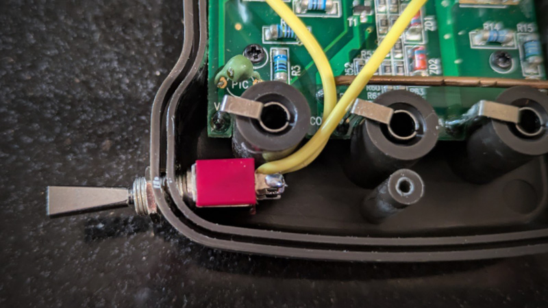
On his first try, he successfully drilled a spot for the SPST switch. To fit the switch into the multimeter’s rubber bumper, he used a circular punch, although his second hole wasn’t as clean as the first. Despite this minor setback, the modification worked perfectly, giving him complete control over his multimeter’s backlight without the original 15-second timeout.
This project follows a tradition of inventive multimeter hacks. Other enthusiasts have made similar upgrades. An older hack involves adding an external display to a multimeter. More recently, we wrote about upgrading your probes. Notably, adding Bluetooth for data communication showed how diverse and creative these modifications can be.


There is a reason why there are no metal parts protruding from stock multimeter cases. There can be major arcing inside and multimeter has CAT rating precisely because it can contain it without posing a threat to operator.
Usually a Multimeter is insulated and tested for up to 1000V. There is no conductive Component on the outside of the Casing. If you destroy the housing, this insulation in not guaranteed anymore. if you further use a component which is not rated for this voltage you are in Danger!
If the swich is not galvanic insolated, it will kill you if you try to measure a high voltage! Dont do This.
Better you use a Reed-Switch on the inside, and a magnet on the outside.
This is the way. I’ve tried to find specs for such switches (e.g. RS 734-6990), but they’re only rated “1000 Vrms at sea level”. No CAT rating (:
Maybe we can 3D print a little captive slider with embedded magnet, that’d be sweet.
i made one of those, to help a little light survive some outdoor weather / water. and the linear slider is difficult to get right. you want it to rub so it doesn’t just flop on and off with tiny motions, but you don’t want it to rub so hard that the switch tends to jam. there might be a good hack but for my purpose i found a push button switch that doesn’t mind getting wet occasionally instead.
the switch i wound up with has a plastic cap so it would arguably be a tiny step up in isolation from the one used here :)
This is a dangerous modification! According to the pictures this multimeter is rated CAT III, so suitable for basic, domestic mains work. However with this switch with metallic parts exposed you are bringing unknown potential(s) from inside the meter to the outside. If something goes wrong this could be letal. There is a reason why PC interface for multimeters are always optical to ensure galvanic separation!
Am I looking at a wire that might be rubbing its insulation to the center connector metal part during use? Or am I just seeing things?
Consider this “brutal honesty” – it looks like feces ! wtf with the wire gauge and routing ? how many amps does the display light take ? from the looks of the wire, plenty…. smh …
As for the other comment about cat-iii, i wouldn’t worry about it – looks to be a cheap chinesium product..doubtful it’s a legit rating…wouldn’t be using it around industrial 480/600 v equipment….not unless you’re wearing a 40 cal arc flash PPE.
CAT there probably means CATastrophe
come on. a little ‘hack 101’…the rating for the wire that matters is not the number of amps but rather whether you’ve got a little bit of it sitting on your workbench at the moment :)
Could have done it with a 555.
I got a multi-USB power adapter, meant for charging phones and the like, and even a wireless charger on top. It had a nice display that would tell you how much current each port was drawing, and what voltage the device had negotiated. In all, it was exactly what I wanted for my bench, except that it was intended to go on a bedside table or something, and the display would shut off after 30 seconds. You could wake it up by shaking it, but that wasn’t really what I had in mind.
Cracking it open revealed that the movement sensor just grounded one of the microcontroller pins. Nice and simple, easy to interface with. I wasted a bunch of time trying to get one of those C005 timer modules to work with it, but the output pulse was just too short for the microcontroller to catch. Eventually I realized that the solution was the same as it is for all projects, a 555. The legs all got folded under, the capacitors went on top, and I used SMD resistors. It ended up being quite compact. A little heatshrink and it was no problem to stuff it into the case of the charger. It’s been working great ever since.
Turns out the answer really was a 555.
Came to post 555. 😆
But srsly even a latching circuit tied to the main ‘on’ circuit and one of the existing soft press buttons would do.
terrible choice of switch – very vulnerable to getting broken. Slide switch would have been far better
A better approach would have been adding some latching logic maybe from a small mcu or logic gates, and picking up the signal from the backlight push button. An MCU could have an auto-off function after some time, maybe to match the auto off of the multimeter itself.
A magnetic reed witch would have worked, and not destroyed the CAT III rating of the meter, or the safety. Then again, this meter might “say” CAT III, but I would not trust it. There is a reason people pay for Fluke.
Nothing above 48V AC / DC is what I would “trust” this meter with.
A metal switch so close to the input leads.
Not trying to be mean here, but its a matter of safety.
I’ve used to do something similar with my uni-t ut33d. there was this pretty much useless HOLD switch, so i’ve cut the traces and repurposed it as on-off switch to turn it off without having to turn the selector wheel every time i wanted to check progress of battery charging (which would risk setting it to current measurement and burning the fuse)… It was even possible to use razor to scratch the “HOLD” label off only keeping the middle “OI” part, which is reasonable label for on/off switch :-)
Repurposing existing switches is bit safer than introducing new metalic switches to chasis. At least if you wire everything neatly and keep internal separation distances…
I like this approach a lot over the botch seen in the article.
If you’re so worried with external contact with the lever, there are covers and you can use a couple of pieces of heat shrink tube. Most times the lever is insulated from the contacts, but I check my stuff. Otoh, if I’m probing something, unless I am using alligator clips, I aint holding onto the meter.
The meter has a OFF position so the easiest way to accomplish this is a wire without switch.
Yeah just have it always on when the multimeter is on, that’s a more elegant solution
Some multimeters have i2c eeprom with configuration values which includes backlight timeout. One example http://www.kerrywong.com/2016/03/19/hacking-dtm0660l-based-multimeters/
This. That would be a hack worth hackaday readers time. But we are served with such a stupid butchery instead. Shame.
Yep, that’s basically what I did with my Voltcraft VC-330 clamp multimeter (identical in all but color to the UNI-T UT210E). It’s been a few years, but as I recall, in addition to changing the backlight time-out, I also changed the content of the EEPROM so that it’d start in DC voltage measuring mode, instead of AC (the default). I might have also squeezed a few more digits out of the clamp ammeter, so it can display single-digit milliamps, too. Some calibration constants may have been in there, too…? It was a fun and educational experience, tweaking that meter, one that has paid me back many times over.
I agree with several of the others: this “hack” might get the user the result he wants, but at a potentially steep price, namely that of safety. I hope he never passes that meter along, or allows anyone to borrow it, because I would NOT want to be held responsible (legally OR morally) for the possibility of electrical shock or other damages that could result. There are other, safer ways to accomplish the same result; this was probably the least safe method. It’s definitely NOT the level of hack the majority of us here on Hack-a-Day expect.
In addition to everything already mentioned about the CAT rating: The two wires are in contact with the DC shunt. This shunt can heat up and melt the insulation. Why do you think it is mounted off the PCB?
There are dirt cheap capacitive touch modules (TTP223) where you wouldn’t even need to modify the case and still being on the safe side.
https://aliexpress.com/item/1005003358582325.html
More the question is… why was this even posted. Not a hack/mod/cool thing. It’s junk.
But did incite a decent rant :)
Why a backlight at all, working in poorly lit areas used to be a problem. Now we have all kinds of LED lighting to use, cheap versatile carry a few. My work spaces are lit with diffuser only “TV’s” no shadows as well as “luxo” type spot LED’s. I can always read my Fluke and rarely need to open it up and change the battery.
What about a switch to mute the annoying buzzer?