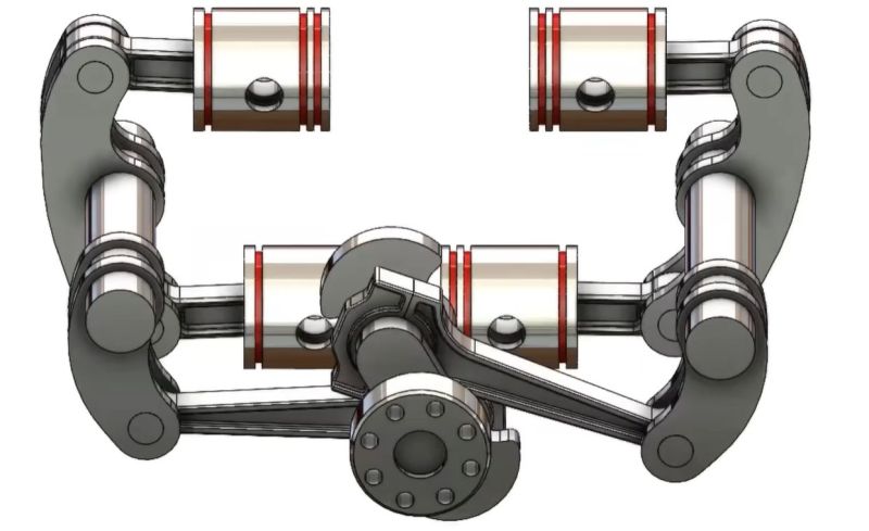
Converting the ignition of a fuel-air mixture into usable mechanical energy lies at the core of a dizzying number of internal combustion engines developed over the course of more than century. Although typical piston engines with a cylinder head and valve-train are the most common by far, and even rotary engines are quite well-known, the opposed-piston engine design is significantly more obscure. In a recent video by [driving 4 answers], this type of engine is covered and why it’s actually a pretty nifty ICE design with many benefits.
Above all, the design is mechanically far more simple, as it omits all the valves and timing-related hardware of the typical four-stroke ICE. Each ignition event pushes against two pistons at the same time, allowing for more of the kinetic energy to be converted into usable power, as well as enabling largely vibration-free operation in a more compact package, especially in the case of the Asender design that eliminates the second crankshaft of the Achates design. This makes the Asender rather similar to the 1914 Simpson’s design.
Despite these many advantages, opposed-piston engines have mostly led a quiet life in industrial and military applications, including tanks, submarines and airplanes. This is where the video also sees their continued use, but as a 2021 article in Autoweek suggests, we might be seeing more of these engines in everywhere from trucks to cars as well. Even if it’s only in hybrid cars where it would be in a generator role, there are many reasons why this ICE design would fit right into certain roles.


The Cummins ACE is a recent notable opposed 4cyl:
https://mart.cummins.com/imagelibrary/data/assetfiles/0059584.pdf
this is why I love my Subaru engine, even if it burns oil and only gets 28 miles per gallon.
Your Subaru doesn’t use opposing cylinders. It has 4 cylinders that push against valves in a cylinder head, with one combustion stroke for each cylinder, just like every other car engine. In Your car, the cylinders are arranged in a visually similar way, but they push inward towards each other. The opposed cylinder design works totally differently, where the cylinder faces come together to compress the mixture and push away directly on each other with each combustion. 1 combustion, two pistons move away from the single blast in a shared long tube.
Note that subarus aren’t opposed piston: they’re flat, but only one piston per cylinder.
And dayammmnnnn have I gone through a lot of head gaskets on my soobs.
Subaru only makes the Boxer engine which is a modified flat engine design, they use a sharper angle for the pistons
I had the same thought. It also means that calling Subaru engines “boxers” is a misnomer. Boxers are actually opposed piston engines because the pistons look like they’re boxing.
They are not opposed piston engines. The two pistons are not converging and diverging within a single cylinder. The correct term is horizontally opposed engine. their cylinders are arranged in two banks on opposite sides of a central crankshaft.
Almost all Subaru vehicles are equipped with a SUBARU BOXER engine, which is a signature feature of the brand. Their horizontally opposed engine design allows pistons to move in a “punch-counterpunch” motion, providing a lower center of gravity for improved balance, stability, and handling.
Note the difference between Boxers and other opposed engines is the crankshaft.
VW engines (only ones worth mentioning) run two connecting rods on each journal, like most V8s.
Boxers only run one rod/journal and have a second journal 180 degrees offset.
Boxers don’t have any lower CG than any other opposed engines.
Just lower vibration.
Most light airplane engines are boxers.
Make sure the cylinder liners are above the block deck, so it imbeds intro the head gasket
You can. Keep your oil burning subaru with my compliments
Subaru engine is not quite the same as the engines discussed here. A Subaru still has one crankshaft and overhead camshafts(and two heads). Further, a Subaru is a four stroke engine.
If the goal of an ICE engine is just to generate electricity in a hybrid car, why even bring the power out to a crankshaft? Why not simply let the Pistons move magnetic fields and generate electricity directly? One could easily imagine putting combustion cylinders with opposed Pistons inside that also contain magnetic devices being wrapped by conductors that take away the ing. AC. If the cylinders and perhaps Pistons are made out of ceramic and are non-conductive, why would this not work? I’ve been wondering about this for years and this is the first time I’ve ever said anything in public about it, but it seems like a really good idea if you have to have ICE.
It’s hard to contain explosions and get enough compression just with power of a magnet or coil. You would need ridiculously strong coil. There are free piston versions (where piston is shuttled alternatively between two ends), but then you have problems with cooling for that piston. In some normal engines, there are even special nozzles that spray pistons with oil from underneath to stop them from melting.
Also, if you have one piston, it will introduce A LOT of vibration without counterweight. If you have more, good luck synchronizing it with magnets.
Not only that, not sure on the exact temperatures, but (permanent)magnets loose there (magnetic) strength at higher temperatures, plus strong magnets are brittle, not a property you’d like in such an environment
You are correct. Magnets wouldn’t be efficient in such a violent environment.
I believe that is called the “Curie Temperature” and it varies with magnet composition.
This is a crap idea for all sorts of reasons but demagnetization probably isnt a valid one.
Curie temps of common magnets
Samarium Cobalt (SmCo): 700°C – 800°C+
AlNiCo: 525°C – 850°C
Ferrite/Ceramic: ~450°C – 550°C
Neodymium (NdFeB): 310°C – 400°C
Unless youre trying to put the magnets IN the combustion chamber I dont see the magnets running into those sort of temps.
I think you missed the idea.
Embed a magnet in the piston, have coils around the cylinder….
The magnet will induce current in the coils.
Be careful with the curie point. Permanent Magnets lose their magnetism above a certain temperature.
“Neodymium magnets (the super strong ones) lose their magnetism around 310-400°C. That’s lower than ceramic magnets (450°C) and SmCo magnets (700-800°C). ”
wikipedia.
Part of the operation of a multicylinder ICE is that the power stroke in one cylinder drives the other stroke for the additional cylinders. That is most effectively done through a common mechanical linkage – the crankshaft.
If you are driving return and exhaust strokes electromagnetically, for the purpose of generating electricity electromagnetically, the numbers in your energy budget are never going to add up, and you will always be operating at a loss. Heat, friction, resistive and inductive loss. You cannot beat entropy.
Thanks for a good description of the problem. But fwiw you always have loss, you cannot beat entropy…but the thing is, is your output large enough to justify the inputs? Is the loss so great that it cannot operate? Surely the electromagnetic exhaust would have losses, but so does the mechanical exhaust. The question is just comparing the losses to eachother, and to all of the other little challenges in an ICE.
I would think these type engines might lend themselves to be put inside wings, avoiding nacelle housings.
Propellers would stick through wing leading edges perhaps.
The engines could be on a track–to slide to the fuselage for repair and removal…each cell electrically powering the motors in the wing leading edge fronts….coils right behind the wing leading edge also serving as de-icers.
The ICE cells thus don’t have to be part of the aircraft
Yes.
The efficiency of a linear alternator-actuator that replaces the crankshaft of an engine with a solenoid would be extremely terrible. First of all the alternator part of the deal would not be able to stop the piston from flying out, because the induced current at zero velocity is zero. You would have to apply power against the piston to stop it, turn it around and throw it back in, then compress the charge, etc.
In a normal engine, this happens automatically with the energy stored in the flywheel, which is lacking in this setup. Free piston engines usually employ a stiff return spring of some description. Metal springs wouldn’t last, so compressed gas is very typical. These engines work because the piston is a mass on a spring that keeps oscillating back and forth for a while without power input, so it can do the intake and the compression and the exhaust strokes with the energy stored in the spring. The downside is that it only really works at one speed, and it’s very difficult to get it started, or to keep it going really since the gas spring needs a whole system of pressure adjustment and replenishing leaks… There are some such engines, but they’re quite complicated.
Permanent magnets could be used for the return spring, but strong magnets get demagnetized with heat shortly above room temperature, and don’t deal well with shocks either.
Here we have a free piston engine that is working as a gas generator for a turbine:
https://www.youtube.com/watch?v=02IP1CaoLFA
While interesting, they have all the emissions issues of a two stroke plus added complexity and oddball packaging. Fun to watch animations of them, especially the Napier Deltic…
Two strokes? Eww yuk.
And sure you can get of all those valves and cams and what-not, but look at the size of those rockers in the picture. Lol.
The engine was very common in Australia in the 50’s – 60’s. We called them the Commer “Knocker”. Diesel, Three or Four cylinder, so six or eight pistons each pushing a rocker arm connector rotating the central crankshaft. The combustion was very loud that why it had the nickname “knocker”. You heard it coming. Was very good torque for hills, fuel efficient and popular in Australian long haul trucks and cross country trucks, and buses. Commer trucks was part of Rootes Group.
This exists and multiple companies have prototypes, but they don’t seem to be making much progress towards production. https://en.wikipedia.org/wiki/Free-piston_engine
The pistons are just one component in a huge ecosystem we call “the engine”. The crankshaft serves as a sort of common bus for power, enabling related systems like the alternator, oil pump, fuel pump, etc. Remove the crank shaft, and you have to redesign all those uncountable ancillary systems instead of using off-the-shelf parts. It’s doable, but productionizing it could take decades.
And who knows whether gas will even be an affordable consumer product in a few decades.
Yup, there are designs dating back to the 1940s
https://en.wikipedia.org/wiki/Free-piston_linear_generator
Magnets don’t like to be heated. You should look into Free-Piston Engine Generators. Two opposing combustion cylinders with a linear generator in between.
In my hybrid, the point of the electric engine is to assist the ICE one in order to be able to optimize the whole thing for efficiency first, so you don’t have to compromise for torque. Using ICE engine only as a dumb generator for an electric drive-train would have terrible mileage (but impressive torque: See diesel-electric trains)
See also the Nissan Qashqai ePower or the latest MG HS PHEV. And they drive just fine thanks.
OK, funnily enough, [Technology Connections] released a video JUST YESTERDAY talking about why hybrid motors work the way they do.
https://www.youtube.com/watch?v=KnUFH5GX_fI
This. The most efficient thing is to change the rpm as needed without changing the energy from motion into electrical and back into motion. Since purely mechanical ways of doing that have too much friction or other disadvantages, then the power split device is better because only the power needed to change the ratios has to pass through the electrical side, yet you don’t need many stages of gears.
Free piston APUs exist, and they have the advantages you describe, but I don’t know of any commercially available ones. If you want to go further, there are also free liquid piston engines, for pumping water.
Interesting but it made me think – momentarily there’s a plasma in the combustion chamber. Can’t we harness some of the electrical energy in that too?
The pinnacle of this is the Napier Deltic engine used in UK locos in the 60’s.
Originally developed for torpedo boats during the second small disagreement.
It can be described as 3x V6 engines, each using the other 2 as cylinder heads.
Yes, the Deltic is my favourite design of internal combustion e ngine!
Indeed, their industrial applications didn’t list railways.
And a rebuttal from an actual engineer: https://www.youtube.com/watch?v=NIxFHVZ_sGk
Even if you know nothing about engines all you need to know is opposed piston engines are two stokes – eww yuk.
the atkinson differential engine was fourstroke. If you were willing to accept a low efficiency flathead or T head poppet valve design you could certainly make a 4 stroke i imagine.
https://www.youtube.com/watch?v=lBIHTEJctu0
The atkinson was used in early ford escape hybrids. They used a 70hp electric “traction” motor to offset the lack of power and also to start the engine. They also incorporated a balancer shaft assembly below the rotating assembly.
https://www.enginediy.com/products/m14-1-9cc-mini-4-stroke-gas-engine-internal-combustion-engine-model-atkinson-differential-opposed-piston?srsltid=AfmBOooQK2pgVwW4i_HDlrWuLql3bzCv_KW5yYYB2Xl7XMRb_PLzdEWI
Opposed piston engines can be 4 stroke.
That is not true, and it is also not true that it is that rare in motor cars. Examples for include Citroen GS/GSA, 2CV, Porsche 911, Subaru WRX (in fact, most Subaru models), Alpha Romeo 33, Alphasud, VW Beetle, Ferrari Testarossa. Far more common than rotary (Wankel) engine examples I think, contrary to this article’s claim..
I think you misunderstand what is being implied here.
The engines youve cited are horizontally opposed engines, or “boxer” engine, features pistons arranged in a 180-degree layout, facing away from each other on opposite sides of a crankshaft. These are, as you have stated quite common.
What is being discussed here is Opposed PISTON Engines in which two pistons move toward each other in a single cylinder, creating a shared combustion chamber between them.
Two very very different beasts.
These are quite rarely seen in automotive applications. The only examples I can find are The 1904 Gobron-Brillié, The 1950s and 60s saw some trucks equipped with a diesel Commer TS3 knocker engine of this variety. And , while not in production, Achates Power has tested a modern, high-efficiency opposed-piston engine in a Ford F-150 prototype.
Thanks for putting him straight.
He really missed the point.
I was in the UK Army a few years ago and “went into battle” with a FV432 APC
These were powered by a Rolls- Royce diesel/multi fuel, opposed piston (6) engine that used to rev so smoothly, it was like a turbine. https://en.wikipedia.org/wiki/FV432
Two stroke diesels are a whole different animal than two stroke petrol (gas) engines. The induction gas is just air so you can use a blower to push air through the cylinder to purge the cylinder without the kind of bleed through of fuel / air mixture you’d get with something like an old motorcycle engine. (Here the crankcase is used as the inlet pump — its a pragmatic design but, as you say, “eww yuk”.)
A well designed diesel is potentially a very clean engine.
Other’s have mentioned the Napier Deltic engine. Its an extremely elegant design, a way of getting a lot of capacity in a very compact space. It also solves the problem of opposed pistons without all those reciprocating linkages and their associated bearings. (The fact that the overall engine is balanced doesn’t mean that there’s significant imbalance internally which leads to all sorts of bearing design issues.) The only snag I can envisage is that inverted cylinders could have problems purging oil, especially during startup.
But….but….why are we talking about IC engines in 2026? They’re still essential, they’re still being refined but for vehicle use they’re effectively obsolete.
Could this design work with diesel?
Yep. Already been done
https://en.wikipedia.org/wiki/Commer_TS3
Just a “thank you” for a clear, even-handed, explanation of two opposed-piston configurations. BTW, since continuously-variable transmissions are practical for small engines, would it be feasible to make one effective for ameliorating the narrow torque range of the opposed-piston engine?
Uhh, what? Anybody wanna ‘splain how that’s supposed to work?
I expect that the ignition occurs between them. The tops of the pistons are close together when the event takes place.
The tops of the pistons are as close together as the expected compression ratio demands.
The diesel comer ts3 had a compression ratio of 20:1. Each piston traveled ~60mm for a total of 120mm stroke with a ~6.315 mm gap at full compression.
If you were to build for a 10:1 compression ratio (common for non diesel IC engines The same 60mmX2, 120mm combined stroke length would require a gap of ~13.3mm
This.
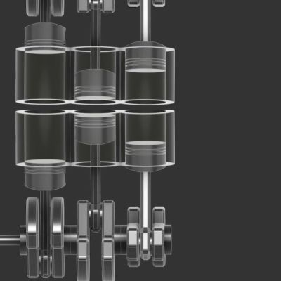
Imagine a cylinder
put a piston into each side of the cylinder
detonate an explosion between the two pistons
capture the kinetic energy as the pistons are driven apart.
Thats how it works.
In a traditional IC engine you detonate and the piston is driven in one direction while the force and thermal energy of the other direction is absorbed by the head. You then pump coolant into the head to relieve that wasted energy
The opposed piston engine clearly captures more of the kinetic energy.
How, exactly, does the head absorb any force? It doesn’t move.
Like all piston engines you lose energy on the return stroke. The “captures more kinetic energy” is mostly bollocks. That’s why rotor (misnamed rotary which is a different beast) engines exist, they don’t lose kinetic energy as the rotor never stops and goes backwards like pistons. They’re a nice idea in theory but failed in practice as well.
If you punch a brick wall, despite it not moving, it will absorb force from your strike. Thats physics. An engine head is no different.
The combustion process creates high-pressure gas that pushes down on the piston, but this pressure also acts upward on the cylinder head. The head must withstand thousands of pounds of pressure per square inch, temporarily storing this as stress before transferring it to the cylinder block via head bolts.
If only does work (aborbs energy) though if it moves. Does it move appreciably? (ignoring the heat absorbtion for a moment)
Doing work is utilizing energy
Energy can be dissipated without accomplishing work.
An object does not have to move appreciably to absorb energy. If an object is perfectly rigid and unmoving, it still absorbs the initial impact force and transfers it entirely to whatever it is resting on.
This can only have been written by someone who has forgotten, or never learned, the difference between force and work. The pressurized gas does no work on the cylinder head or bore. No mechanical energy is wasted on stationary metal.
The claim of a thermal advantage is only slightly less implausible, since there are more engineering details on top of the simple physics, but it’s still silly. The cylinder head and piston are made of the same materials and have the same maximum temperature. The piston has to remove just as much heat per square cm to keep its metal from melting as the cylinder head does. Furthermore, cooling pistons is harder than cooling the head — splashing or spraying oil on to the back side of the piston takes quite a bit more work (in the mechanical sense) than pumping watery coolant through nice, big passages in a chunk of aluminum, and that work is wasted energy.
I’m glad that Mazda is bringing back the rotary even if it’s only in the form of a hybrid so it’s just charging batteries. I hope the 2 stroke is coming back. The most power from the least amount of displacement. With new oil technology the exhaust fumes are relatively clean. And it’s much more fun. Especially if the batteries aren’t in between the engine and the wheels.
With supercharger scavenging a two stroke doesn’t burn any more oil than a four stroke.
What about the Subaru Boxer Engine?
boxer engines features cylinders arranged on opposite sides of a crankshaft, with pistons moving in and out together like sparring boxers
this article discusses opposed PISTON engine=two pistons in ONE cylinder, These pistons move towards each other during compression, then after detonation between the piston heads, they move away from each other.
Is this AI? It reads like it’s authoritative, but has no backing in reality.
Pushing against two pistons isn’t more efficient than one.
The lack of valves isn’t inherent to this engine, typical two stoke engines have no valves. Just like these opposed piston two stokes.
Is this AI? It reads like it’s authoritative, but has no backing in reality.
Opposed-piston engines lack a cylinder head, reducing the surface area-to-volume ratio. This minimizes heat loss to the cooling system, allowing more combustion energy to turn into useful work.
Thanks. This is about the only efficiency advantage imaginable. I think it’s also related to the inferior efficiency of a Wankel–more surface to volume than a regular piston engine.
Why is it that every time I start learning about a topic, you guys do a piece on it like the next day. It’s frickin weird bro stop following me lol
Anyway, I was just learning about a successful version of this engine that ran for a decade in semi trucks in Australia and NZ in the 50’s called the Commer Knocker TS3. I wasn’t actually aware that there were any commercial applications for this engine topology so this was kind of exciting. Supposedly, they were even able to run a long term test for the fuel mileage on one, and it returned a result of 20.25mpg! Which sounds insanely impossible when you consider that modern diesels can’t hardly break 10mpg!
Link to one running:
https://youtu.be/BStb4hWcTpg?si=wITy09dqRYrWp-Pk
Sorry, HERES the running one
https://youtu.be/JrAoj5Cuu68?si=PRJsqruFpTMWfDdM
And an actual truck
https://youtu.be/e0sLp7wvq60?si=pnxUu3SeOEyHHf22
These diesel engines were everywhere in Australia when l was growing up. 4 cylinder and three cylinder, in large long haul trucks and buses, and smaller 7 tonne trucks.They lost market in Australia because the US truck brands forced them out. The engines were common from 1910 to 1960’s. Good torque for hills and economy.
No need to watch the video beyond 39 secs. Fatal nonsense found. No energy is consumed by static pressure against sratic cylinder walls.
Or against the head as some think. The dude in the video has no idea, he just repeats Wikipedia and press releases.
Ok, so hear me out, what if we added a hair more complexity and went with a rotating sleeve valve setup to make it 4 stroke?
I get it, 2 strokes are more efficient, but emissions standards are a thing.
Add another cylinder pair, go with rotating sleeve valves, and you’ve got an engine with one cylinder always firing. There’s a guy already working on rotating sleeves for heavy diesels to reduce friction, and we know sleeve valves work.
The Spanish company Innengine it’s actively developing one. You can find some youtube videos where you see it working at high revs with no vibrations at sight! neither the wires vibrate (at simple sight)
https://innengine.com/es/
They are a small company from Granada, you know, where is “The Alhambra”.
Now they are in a point that a big company has “bought” it for developing and testing. They say they are focuse mainly for airborne (and the other options as range extender and so).