I’ve talked a fair bit about USB-C before, explaining how it all works, from many different angles. That said, USB-C is just the physical connector standard, plus the PD part that takes care of voltages and altmodes – things like data transfer are still delegated to the two interfaces you invariably end up using on USB-C ports, USB 2, and USB 3.
You might think USB 2 and USB 3 are tightly related, but in many crucial ways, they couldn’t be more different. I have experience working with both, and, as you might guess, I want to share it all with you. You might be surprised to hear there’s plenty to learn about USB 2 in particular – after all, we’ve had it hang around for 30 years now. Well, let’s make sure you’re fully caught up!
The Ingredients
USB 2 is a point-to-point link – one side is “host” and another is “device”, with the host typically being a PC chipset or a single-board computer. USB 2 relies on a single pseudodifferential pair. It’s “pseudodifferential” because the wires don’t just do differential signaling – they also use digital logic levels and pullup/pulldown resistors to signal device presence, especially in the beginning when the USB link is still getting established. Indeed, you can imitate a USB device’s presence with just a resistor.
This differential pair is half-duplex – it’s used for communications back and forth, but only one direction of data transfer at a time. Just like I2C, USB 2 requires the host to initiate all communications. The host has to poll the devices on a regular basis to receive data, a point that regularly gets brought up by defenders of PS/2 keyboards.
You know that USB ports come with a a 5 V power rail, but there are plenty of 3.3 V USB devices, too – in fact, most USB devices operate on 3.3 V internally. At its core, USB 2 requires 3.3 V-based signaling – which is why, when powering your RP2040 from 1.8 V, you must still provide 3.3 V if you want the USB peripheral to work.
In short – if you plan to put USB devices on your board, get some 12 MHz crystals and you’ll likely be well-prepared. Why the 12 MHz specifically? It’s directly related to a common USB 2 device speed, of which there are three.
The Three Generations
You might have heard of USB 1.1 and USB 2.0 standards, supposedly, being entirely different beasts – that’s true, but nowadays this distinction can be misleading. In practice, there are three versions of USB 2 you should actually distinguish.
These three versions are: low-speed at 1.5 Mbps, full-speed at 12 Mbps, and high-speed at 480 Mbps. The USB 1.1 standard only described the 1.5 Mbps “low-speed” and 12 Mbps “full-speed” devices. The USB 2.0 standard covers both of these modes, too, but also adds the 480 Mbps “high-speed” mode, which operates quite differently on the hardware level, and a number of other improvements. Modern devices are most often USB 2.0, even if they’re 1.5 Mbps or 12 Mbps, which is why I don’t use USB 1 to refer to these kinds of devices – it’s rarely true.
lsusb -t and lsusb -v, and on Windows, you can use something like HWInfo. Bottom line is – the device speed is what matters, and the standard version doesn’t matter as much, whether it’s 1.0, 1.1, 2.0, or a secret fourth thing.
Flash drives and Ethernet or WiFi adapters are bound to be 480 Mbps, whereas devices like mice, keyboards, fingerprint readers, or USB-UART adapters are typically 12 Mbps. The three speed standards are expected to be compatible between each other – for instance, 480 Mbps devices are expected to be able to fall back to lower speeds if needed, and 480 Mbps hosts are designed to support 12 Mbps and 1.5 Mbps devices. The USB guarantee is that you can plug anything into anything, and generally, it works out.
Microcontrollers, sadly, rarely reach 480 Mbps on their USB peripherals, as much as that would make all our Pi Pico logic analyzers shine. There’s some fundamental reasons for this – 480 Mbps signaling is entirely different from 12 Mbps and 1.5 Mbps, with the 480 Mbps signal looking much more like a modern day differential pair, and 12 Mbps signal being firmly 3.3 V-referenced, in effect, a logic level signal a la UART. This is why you can easily capture lower-speed USB with a logic analyzer or a Pi Pico, but you can’t do that for 480 Mbps anymore.
Of course, some hosts don’t handle the inter-speed compatibility aspect well. This is generally a matter of driver support – famously, the Raspberry Pi 1 Model A, without the onboard USB hub and Ethernet chip, initially didn’t work well with mice and keyboards and other low-speed devices on its sole USB port. Specifically, its only USB port that was connected directly to the SoC. On the far more popular Model B, the onboard USB hub acted as a “proxy” of sorts, handling the lower-speed USB devices internally while keeping a full-speed link to the SoC, so the SoC on the Model B only actually talked to a single full-speed device and the driver issues never surfaced. The driver quality has come a long way, and the Pi Zero no longer experiences this problem, however, but other devices of yours might – if that’s the case, remember that you can always add a hub in between.
On the other hand, over a dozen years ago, when high-speed 480Mbps devices became more popular, PC front panel cabling was often designed for the somewhat more lax physical requirements of lower-speed USB, and even stretching those requirements. Remember the advice to plug your USB device directly into the motherboard port if it’s not working well? Often, the shoddily built front panel cable was the reason for that. Not to mention that most front panel boards never had any capacitors on them, something that dramatically helps your USB device stability when you’re adding a host port.
Oh, and the usual reminder, these data rate numbers are megabits (Mb) per second. If you want megabytes (MB) per second, you want to divide by 8, and then some more because of the data transfer overhead. In practice, if you have a 480 Mbps flash drive, expect transfer speeds of 30 MB per second or so; same goes for USB2 WiFi and Ethernet adapters, of course. This was another well-known problem with Raspberry Pi boards before Pi 4 – lowered transfer speeds when using Ethernet and USB devices at the same time, since all of them had to go through a single 480 Mbps link to the SoC. Then, with the Pi 4, the SoC acquired a PCIe link and a separate GMII link for Ethernet, and nowadays this complaint is history.
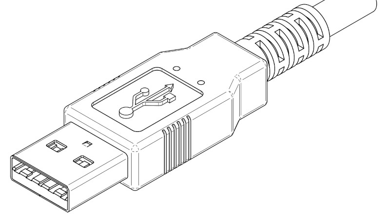
Conventions, Pinouts, Colours
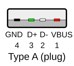
Red and black are 5 V power and ground – a good ground connection is required for USB to work. Wondering just how much current you get? The answer is, 500 mA is guaranteed, and 1 A to 2 A is exceptionally likely; I’ve talked about it in more detail in this article.
Green and white are D+ and D-, the two pins in the diffpair. Again, preserve these colours where possible! Cables are very likely to follow these specifications, and if you memorize the colours, you can easily wire up your own tech in no time. You can remember the colours through a mnemonic – green is summer (life, +), and white is winter (death, -). The standard pinout for USB-A and MicroUSB/MiniUSB connectors is VCC–D-–D+–GND, and it’s easy to remember too – you sit next to a fireplace (power) in winter, you go to the beach (ground) in the summer.
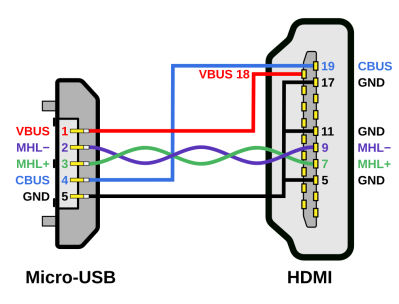
ID pin right next to GND, a pin originally intended for indicating whether your phone’s MicroUSB socket should switch into host mode, and later growing into a proprietary mess of a pin. In those dark times, it was used for video over MicroUSB standards like MHL, debug port summoning using bespoke resistor values, and even combined charging and host modes – none of it documented or prominent in any reasonable way. You rarely ever need to bother with the ID pin – nowadays, USB-C does that the ID pin ever could and way more, and it’s clear the primitive proprietary ID pin signaling standards have inspired the well-structured standard that is USB PD.
Unlike some nice standards like PCIe and USB 2, you have to connect + to + and - to -, no crossing wires. It won’t hurt anything electrically if you flip them, though, so if you’re reverse-engineering a device with USB 2 on a custom connector, feel free to connect it one way, plug it in, check dmesg or Device Manager. If you see enumeration faults, just unplug, flip the wires, and plug it in again. One warning, don’t solder on the data wires of a device plugged in, that can easily kill your device! A flipped connection where both wires still make contact is guaranteed to still result in enumeration, just that it will error out – you can use that as a way to check your connections, too.
Which connector do you use for USB2 on your own devices? Without a doubt, USB-C is the best and most universal choice; don’t be like Raspberry Pi Foundation with Pi Pico boards, forcing us to tap into our ever so dwindling supply of microUSB cables. Remember, you only need two 5.1 kΩ resistors (or 4.7 kΩ, or two pairs of 10 kΩ in parallel) to properly implement a USB-C device port, or two 51 kΩ resistors to implement a host port. Don’t be a fool, USB-C your tools.
What if you want an embedded USB port, in a low footprint? My advice: you should put USB on JST-SH sockets, just like QWIIC, which is an I2C-on-JST-SH connector and pinout standard that you should also use. I used to put USB on the JST-SH pins in a way that mimicks the USB-A pinout, but now, I use a riff on the QWIIC pinout – GND–VCC–D+–D-. Yes, I told you to use a pinout, but this one is for a good cause – it avoids killing devices if you accidentally plug a QWIIC device into a USB JST-SH port, or vice-versa.
Bringing USB2 Places
You can pull a USB 2 link for up to five meters, in theory, though three or four meters is way more likely. Two meters is the longest that you usually see in USB2 cables on the market. You’ll want seriously proper cables for five meters, of course, because that’s where things start to get touchy. When it comes to link quality, USB 2 can take a beating – until it can’t.
You might have seen USB 2 operate in some pretty bad conditions – dirt cheap USB hubs routed on a single-layer cardboard-backed PCBs, no impedance matching whatsoever. Indeed, you can get away with this more often than not. However, if you’re pushing USB 2 to its 480 Mbps limit, maybe you’re just putting a hub on your board and exposing some ports, beware – you might just get an unpleasant surprise in the shape of USB errors in your OS logs. By the way, on Linux, you can check for these errors by looking in dmesg – run dmesg -Hw to get a view on what’s happening with your kernel, including any USB errors that might occur.
The RP2040 with its 12 Mbps max speed might not have to impedance match, though the Pi Pico does, but if you’re designing a hub and you want stable 480 Mbps, you should certainly remove length differences between tracks in the USB 2 differential pair, and at least attempt to impedance match your tracks – again, treat your diffpairs with respect. Off the board, same goes for making sure your D+ and D- wires are a twisted pair.
That’s enough for today – next time, let’s talk about ESD diodes, USB2 hubs, connectors, debug tools, bitbanging, descriptors, and a fair bit more. At the same time, let’s explore USB3 – USB2’s younger sibling, so alike yet very different.


“[…]I want to share it all with you.”
Thanks!
Agree!
Warcrime is an understatement. Everything HDMI touches, tuns to sh…t.
HDMI is such a pain. Got the datasheets and I2C register definitions?…then you cannot buy the chips. Found someone willing to sell you the chips?…good luck getting the I2C register definitions (sometimes you can get the datasheet though, but still completely useless without the I2C definitions).
Displayport linj training enters the chat…
I’d rather deal with that, than the HDMI licensing thing. Yes license?, yes come in…no license?, no come in… :-)
At least with DP I have no artificial constructs stopping me from using it in my projects.
I never got around to writing firmware for micrcocontrollers on the USB Bus Bus… but I once did hook up the ubiquitous USD 10 Logic analzyer (Cypress CY7C68013) and sniffed some low-speed data going to/from a mouse, keyboard or UsbASP (Based on the bitbanging V-USB from Obdev) I guess that will be handled in more detail in the follow up. I was quite amazed about the details of low level signalling I was able to capture with Sigrok / Pulseview and that simple hardware. From T-states and checksums and keep alive messages, and other stuff that is completely necessary to debug a project, if USB does not work properly (yet) and thus your OS does not log any messages for it.
As for USB 1.1. I thought it was fully obsolete / deprecated and superseded by the 1.5Mbps and 12Mbps versions of USB2
“As for USB 1.1. I thought it was fully obsolete / deprecated and superseded by the 1.5Mbps and 12Mbps versions of USB2”
There also was USB 1.0.. It had been quickly superseded by USB 1.1.
USB 1.0 was in use when Windows 95 w/ USB support was around.
There are probably no more PCs with USB 1.0 ports around, but the situation might be different for USB Mice/Keyboards/Joysticks.
Especially the classic mid-90s peripherals might still have some fans.
Early MS Sidewinder joysticks, ergonomic keyboards, Microsoft Mice etc.
These devices aren’t obsolete yet, except for their compliance to early USB specifications, maybe
yessss and thanks to the backwards compat, these devices will still work wonders! save for having to find drivers for them, of course. My dad’s first thinkpad (390E, I think?) had USB 1.0 and it seems the whole surrounding lineup of Thinkpads did too, so it defo was around for a fair bit, and I wouldn’t be too surprised if quite a few USB chips made back then, stuck with USB1.0. Nowadays though, even on lower-power devices, implementing 1.0 instead of 1.1 doesn’t seem to make much sense, so I can’t imagine there is much if any USB1.0 devices being manufactured. For all we know, the differences might be minor enough, that it could just be a matter of a relabel for quite a few.
I don’t think there are any current that implements 1.1. As far as I have seen it’s 12 Mbit/s USB2, or no usb at all for microcontroller. Bigger systems may of cause implement 480 Mbit/s or even USB3.
Quite surprisingly, RP2040 implements USB 1.1, for one! At least, that’s what the datasheet blurb says – I’m yet to plug one in and look at lsusb.
Some of the earliest iMac also had USB 1.0 and could only support keyboard and mouse. Got an USB flash drive? Sucks, it won’t work on those iMac.
Going to need a citation on that one. You might be mixing that up with OS X Server 1.0 (and the preceding Rhapsody developer releases), which had very limited USB support. It had the following release note:
“Detects USB devices on only one of your computer’s USB ports at a time. To use a USB mouse, connect it to your keyboard or only connect a USB hub to one of your computer’s port and plug all of your devices on the hub.”
nice stuff, but too much raspberries in such article, and “don’t solder on the data wires of a device plugged in” – what?
Naw, most everyone has lots of raspberries sitting around doing stuff. Shoot, I have 6 RPI-5s in things, and several Picos in use, plus a box full of RP2040 boards. I have 8 RP2350 boards already with 2 in use. And a box of all the previous models. It’s a RPI world…. At least around here :)
Common sense on not soldering wires on a device that is plugged into a live computer…. But like ‘warning coffee may be hot’ on coffee cups … For some it may be necessary just to point it out :) .
Enjoyed the article.
Oh come on, who among us hasn’t soldered onto live electronics?
That’s how I found out that my soldering iron has a grounded tip!
“Oh come on, who among us hasn’t soldered onto live electronics?” I feel ashamed but I never had such idea. But when I was a small kid I took a wire and put both ends into AC socket holes. That may be a bit similar?
I did that only once …. :) Lesson learned.
a) mind you, it really helps if I provide practical examples of what I’m talking about, and it’s nice if the examples are relatable to an average hacker. The RPi hardware had some fun bugs early on, it’s what I can I personally heard a fair bit about, and it’s what a lot of people have encountered.
b) this is generally about AC-powered irons, which is the overwhelming majority of them nowadays, and they tend to have some potential on the tip or not be well-protected ESD-wise; and, the USB2 bus is generally a pretty sensitive point – the two don’t mix well. In laptop repair, it’s not that uncommon to see USB2-related failures, probing for such failures using internal ESD diode probing is a well-known fault debug method that can help you track down a CPU fault, and, I have a laptop or two that exhibit the signs of a USB-related CPU failure like this.
On first reading the feeling just grew and at the part where I was informed that Pi5 has PCI-E I was not sure if this is still article about USB or history of Pi models. Also perhaps I noticed it because the article is TL;DR size so extra stuff was more visible. But on second read it is OK. Thank you.
As for soldering the ‘live’ wires, did you also mean to not do it when computer is turned off? Like taking apart mouse while it is plugged into computer that is off and then soldering to usb wires in the mouse. Wouldn’t do that too, but that is indeed not obvious.
“On the far more popular Model B, the onboard USB hub acted as a “proxy” of sorts, handling the lower-speed USB devices internally while keeping a full-speed link to the SoC, so the SoC on the Model B only actually talked to a single full-speed device and the driver issues never surfaced.”
Except that this was also incredibly buggy at initial release. If I remember rightly, some of the time the Pi driver would split up the messages to the hub requesting translation to low or full speed in a way that wasn’t actually allowed by the spec, which would wedge the logic in the hub and cause USB devices to stop working. The Pi Foundation and the community blamed users for these problems originally, claiming that it must be caused by them using inadequate power supplies or the wrong keyboard and mouse when in reality it was simply unable to reliably talk to any keyboard, mouse or other low or full speed USB device via any high speed hub including the onboard chip in the Model B. Some member of the community with a USB analyzer eventually caught the problem.
oh didn’t know that, damn! pretty glad I just happened to give those boards a year-two, guess they have matured beyond that by the time I started tinkering with them =D
“You might think USB 2 and USB 3 are tightly related, but in many crucial ways, they couldn’t be more different.”
Not just that. They’re two independent data links, actually.
An device with both USB 2 and 3 pins can hold two independent connections simultanously.
Modern intel chipsets don’t support USB2 anymore (no legacy block),
but let an external USB3 hub do the USB2-USB3 conversion. Or so I heard.
yesss, I’m about to tell quite a bit about that in the USB3 article ^~^
😃👍
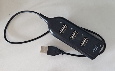
Can you include the cursed “USB 3.0” hubs which have a USB2.0 hub connected to 3 or 4 ports, and the USB3 diff pairs routed to just one of them (with the 3.0 socket)… so the USB3 goes direct to the host, but the USB2 goes through a hub? Most of the cheap usb3 hubs seem to do this :(
will see – if I haven’t already included them =D
Wait what? It’s trivial to find HS-to-FS-and-LS transaction translators, but it’s devilishly hard or next-to-impossible to find SS-to-HS transaction translators.
If you’re telling me that every modern Intel board must include one in order for its USB ports to have their mandatory HS pins, I’m suddenly super intrigued.
Is that supposed to be a joke or something?
Uwe Sieber’s “USB Device Tree Viewer”[1] is the only way to go in this case. Especially in comparison to lsusb, which – I’m sure – is worse than USBTreeView no no matter which argument you use.
[1] https://www.uwe-sieber.de/usbtreeview_e.html
What? You mean there are people still use Windows … for technical work? Yikes!
And working with the command line is great for tech stuff. Rather than all that GUI fluff that is best used for word processors, spreadsheets, email clients, cad, browsers, etc.
you know windows has cmd, powershell, and linux subsystem for windows right?
funnily it is called WSL, not LSW, some hidden joke maybe, in fact running windows layer on top of linux kernel may be a future for microsoft, so the name is only slightly ahead
For many of us, OS is dictated by central IT. For those of us that work in both the mechanical and software worlds, Windows is almost 100% required, as all industrial CAD packages (I think, maybe there’s an exception) only run on Windows. I wish it wasn’t so, but it’s the ocean I swim in.
? it’s not clear to me why you’re saying I’m joking. HWInfo was recommended to me by a friend who uses it for these purposes with as much as lsusb, and, your certainty on “worse” is puzzling. lsusb is more than enough for most people for the overwhelming majority of USB checking tasks, and so is HWInfo.
Yeah…. my comment is too wired/confrontational.
My “certainty” should’ve been “I think” but the reason is that USBTreeView isn’t just a viewer, it’s a quasi-live monitor.
It shows you which devices are dis-/connected, their sub-devices, associated drive letters / mount points, let’s you restart ports/devices, give individual names to devices, “links” usb2/3 companion ports and so on …
And while it doesn’t have an “interactive” use on the command line like lsusb it can still be used without its GUI to write reports.
Like Process Explorer[1] it is one of the programs I’ll sorely miss when switching to Linux…
[1] https://superuser.com/questions/285572/equivalent-to-sysinternals-process-explorer-on-linux
cmd
wmic path CIM_LogicalDevice where “Description like ‘USB%'” get /value
makes command line people happy cause its a good and long one
when i read the usb 1.1 spec a couple years ago i was absolutely astonished by the polling. took me a few takes to accept that it’s totally inescapable if the master initiates every exchange, which is obviously a huge simplifying assumption. after a while i could even convince myself it ought to be trivial to deal and not actually a problem at all. but the real seeing-is-believing is having a keyboard mouse and joystick all hanging off of an ancient (a quarter of a century old?!) unpowered usb 1.1 hub off of a 12ft cable and it works flawlessly. still kind of in awe imagining how many packets it carries all day long saying “poll 0? no. poll 1? no. poll 2? no.” over and over while the input peripherals sit in the corner untouched. nothing gets hot. of course that’s a trivial level of overhead even if it happens some hundreds of times a second.
looking forward to the usb 3 article
I was also surprised by the whole polling thing when I started looking deeper into USB. But your whole PC is toggling a gazillion bits at Giga Hz speed, so a few more bits at a lower speed through a cable does not make a big impression. And the whole polling thing is also handled by hardware, or some “peripheral processor”. I never got around to do some real USB programming for microcontrollers, but from what I understand all this polling is also mostly handled by the hardware, even in small uC’s. You just assign a memory buffer to the USB controller (maybe configure DMA) and your firmware gets a message when a packet has arrived, or it needs to do some other housekeeping.
For learning low level USB stuff, I really like the Obdev firmware stack. It’s very nicely written, and because it’s (nearly) all readable C (with some assembly mixed in) it’s much easier to read and understand then those multi thousand pages of official USB documentation, combined with whatever which way your uC fab devised to put in your USB controller.
I used to think USB was too complicated, and I wished everything ran on some simple RS485 type bus, and that polling was a dumb idea. But now all the hardware is cheap and MCUs have USB controllers built in, and it’s great. I can’t think of much that would make a really significant improvement.
i still like usb2 for its ease of hackery and general simplicity. four pins is all you need.
In regards to maximum length, there are longer extension cables you can get with “repeaters” built in, which are essentially single port hubs. I have an old one somewhere, that was 2.0, or maybe even 1.1. I used to use it as the first section, and then connected the regular extension cable into it, and then a long cable onward to the device. It worked surprisingly well.
These days I have one for USB 3 that runs all the way around two walls of my bedroom, allowing me to get the wireless receiver closer to the keyboard and mouse, increasing reliability. It has repeaters regularly spaced down it’s length. I think there’s three or four of them. The far end even has a power input for powering the device you connect to it.
I have a fiber optic HDMI cable, and that got me wondering. Sure enough, there are fiber optic USB extension cables. They aren’t cheap, but considering what all is crammed into two connectors, and then the composition of the cable itself, that’s not surprising.
Since USB 3 SS is fully differential, it’s relatively straightforward to push it directly to an SFP optical transceiver. The only trouble is that this leaves the USB 2 HS/FS/LS stuff behind, so you need a transaction translator at the other end.
I suppose the commercial fiber products must’ve solved this, I should probably pick one up and tear it apart.
I was thinking of the “looks like a regular cable, but happens to be optical inside” ones. But my casual search found some media converters as well.
USB full speed can be surprisingly robust. I once extended the cable on a webcam with 50 feet of old phone cable. It worked perfectly despite the cable being way out of spec.
Decades ago I wrote a USB stack for the 18F4550. Got about 85% done when I ran out of available flash on the PIC. Never, never, NEVER EVER again. This was my entry into USB, and looking at all the information available in the descriptors (required), I was dumbstruck by the usual error messages on Windows PC’s…namely: “ERROR. An unknown error has occured”. You had to determine there was an error, so why not just print it out so that the user has somewhere to start diagnosing the issue?
These days? Cheap USB-to-UART chip, and off I go…ignorance is bliss… :-)
“You had to determine there was an error, so why not just print it out so that the user has somewhere to start diagnosing the issue?”
Because “if-else if-else” and “try-catch-finally” trees have the ending “else/finally” simply because there may be unidentifiable errors (or at least ones the programmer didn’t anticipate, but at least they anticipated their unanticipation).
Calling shoddy programming “unanticipation” is like ordeing pizza with smegma cheese topping.
Have you used a Google product recently? The last error I saw from them just said “something went wrong.”
I’m going with “war crime” for that first commercial version of MHL. Had to wrap the adapter in aluminium tape and put my Galaxy S2 in airplane mode to get a somewhat stable HDMI signal out of it.
I have run a USB2 wifi dongle with a hacked together USB cable that ended up being 35ft long and going all the way up to the top of an antenna pole on my roof. Ran the dongle as client through a router, and internet from the neighbor was stable.
A nice overview but claiming USB-C as ‘the best’ is I’d say a massive stretch – its a standard that is so convoluted and a compatibility nightmare, with generally expensive cables of dubious performance that are in many ways the modern equivalent of those really annoying power only charging cables that were so common in the past – which just makes it even more annoying to use on all your USB2 only device – now they use the same cables you have to label every single cable you own with its real world performance or your stupidly stupidly expensive actually meets the spec high speed USB-C cable that looks vistually no different to the crap one that only does USB2 stuff is going to be wasted on the device that could be connected with wet string.
Even if you only use USB-2 though it what gain does it really bring?!?!? The connector itself mechanically isn’t really any better either, some plus points some negatives but for USB2 anyway the Mini and Micro USB could be considered better in many ways (the retention in the socket for instance (though micro USB3 is a cursed connector that shouldn’t exist at all) and if you have space for it the larger A and B connectors are very hard to argue against being so much more durable than any of the smaller connectors, and really not that much bigger…
USB now really isn’t much different to HDMI as standards go…
yeah the argument over type C connectors is not very strong and sounds like a consumerist gimmick.
In our neighborhoods, there already are plenty of USB A-B cables literally taking dust as well as salvageable B sockets for our projects (after all, we are on hackaday so reusing material should not be overlooked). Those sockets are very sturdy and they are standard 1 inch pinout suited for easy prototyping.
Using a socket is already a comfort addition to a design though. Many manufactured devices just don’t bother with some removable cable and that’s especially true for USB peripherals.
Let’s just invest on type C where we really need its special features.
USB-C has treated me much better than microusb, which would wear out way before its rated number of insertions in the real world. It’d begin falling out or needing to be carefully positioned to make contact very quickly. Mini usb would keep working despite greater forces, but usb-c is at least decent, even if supporting greater stuff is only sometimes.