When [Rodrigo Feliciano] realized that the reason his seven-segment LED wall clock wasn’t working was because the original TG1508D5V5 controller was fried, he had a decision to make. He could either chuck the whole thing, or put in the effort to reverse engineer how the displays were driven and replace the dead controller with something a bit more modern. Since you’re reading this post on Hackaday, we bet you can guess which route he decided to take.
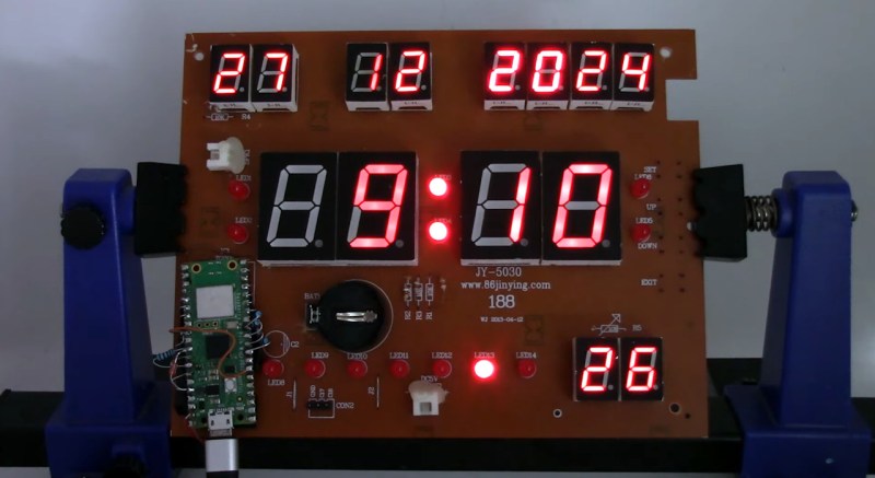
If you happen to own the same model of clock as [Rodrigo], then you really lucked out. He’s done a fantastic job documenting how he swapped the original controller out for a Raspberry Pi Pico W, which not only let him bring the clock back to life, but let him add new capabilities such as automatic time setting via Network Time Protocol (NTP).
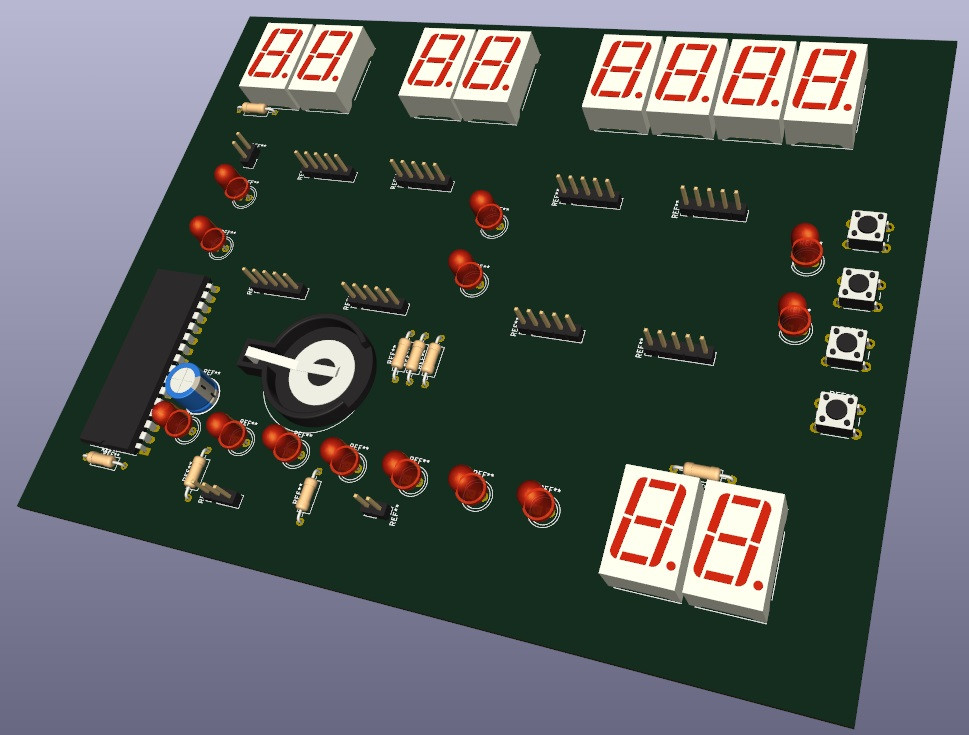 But even if you don’t have this particular clock there’s probably something you can learn from this project, as it’s a great example of practical reverse engineering. By loading a high-resolution image of the back of the PCB into KiCad, [Rodrigo] was able to place all the components into their correct positions and following traces to see what’s connected to what.
Pretty soon he not only had a 3D model of the clock’s PCB, but a schematic he could use to help wire in the Pi Pico. Admittedly this is a pretty straightforward PCB to try and reverse engineer, but hey, you have to start somewhere.
We had high hopes for KiCad’s image import feature when it was introduced, and it’s great to see real-world examples like this trickle in as more folks learn about it.


Interestingly this LCD panel is well known for the meme which claims that a certain day and time was on the display in BTTF. This was generally photoshopped to show a different date from the film. Eventually we passed the actual film date, Pluto was visited by New Horizons for all of 29 hours, and the meme faded to obscurity.
I’m glad I’m not the only one who saw BTTF in this project.
As a fan of BTTF, I have no idea what you written about.
(Sigh!)
And I had no idea what BTTF meant. Well I have now, that is one long and detailed wikipedia page!
It seems to be referring to the famous “future date” from Back to the Future Part II, which showed October 21, 2015 in the film. On that actual date in real life, NASA’s New Horizons spacecraft had already completed its historic Pluto flyby on July 14, 20154.
The New Horizons mission was a groundbreaking space exploration achievement, where the spacecraft passed just about 7,750 miles (12,472 km) above Pluto’s surface after traveling almost 10 years and three billion miles2. This flyby was a significant moment in space exploration, marking the first-ever close-up mission to Pluto and its moons2.
Interestingly, the Back to the Future franchise itself has become a cultural phenomenon, with its time travel themes and memorable characters like Marty McFly and Doc Brown continuing to inspire memes and pop culture references decades after the films’ release1. The meme culture around the film’s predicted future date became a playful way for fans to compare the movie’s vision of 2015 with reality. (according to perplexity.ai)
Ew, AI garbage. At least have the decency to prefix the comment with that if you can’t be bothered to write it yourself.
Nice fix! Although I think you’re overdriving your GPIO pins. You’re using a 100 ohm current limiting resistor, but with 3.3v that means it’s driving around 13mA per LED (given a typical LED voltage drop of about 2V). This is slightly above the top range of the max GPIO current of 12mA. But worse, the common anode will drive up to 7 segments at once. So you risk breaking those pins (as they’re not constantly on but multiplexing, the issue may be slightly less severe). Better to use a BJT or MOSFET to drive those common anodes.
Another thing, from your video it seems the digits aren’t evenly lit. The first two digits of the year are much brighter. Probably an issue with the driving code.
Yes, the currents are higher than recommended, but the pins are multiplexed, which reduces the risks. Ideally, the resistor values should be increased. Additionally, the First two year displays are connected directly to 5V and remain always on, without passing through the Raspberry Pi Pico
“Additionally, the First two year displays are connected directly to 5V and remain always on,”
So, you’ll have to disconnect 5 segments in 75 years…
B^)
Yes, the currents are higher than recommended, but the pins are multiplexed, which reduces the risks. Ideally, the resistor values should be increased. Additionally, the first two year displays are directly connected to 5V and remain constantly on, without passing through the Raspberry Pi Pico.
The first two digits of the year are brighter because they are only wired to drive the segments to produce “20”, with the assumption that this will not operate prior to the year 2000 or after the year 2099.