If you’ve ever worked with I2C, you know its one of those things that makes working with modern microcontrollers such a pleasure. With a few wires and not many more lines of code, you can communicate with all sorts of hardware such as sensors, displays, and input devices. There are even I2C keyboards out there, although they tend to be a bit pokey — and not in the good way as it pertains to keyboards.
But the bt2i2c project from [Roberto Alsina] promises to improve things. With his firmware flashed to a Pi Pico W, you can establish a connection with any standard Bluetooth keyboard and have the keystrokes sent over the wire via I2C. As far as your project is concerned, the input will appear to be coming from a BlackBerry BBQ20/BBQ10 keyboard using the address 0x1F, which means that there’s already plenty of code out there to work with. While [Roberto] explains its not strictly necessary, connecting a ST7789 display to the Pi Pico over SPI will give you some visual feedback on connection status.
As microcontrollers become increasingly powerful and capable of the sort of thing we would once have done on a “real” computer, a project like this has some fascinating potential. We’ve seen a number of “writerdeck” projects running on chips like the ESP32, and it’s not hard to see the appeal of being able to easily pair your favorite Bluetooth keyboard up to one of them.
Modern micro-controllers are absolute marvels, but it isn’t too many projects use one and nothing else. For an example of such simplicity, take a look at [oyama]’s Pi Pico MIDI looper.
It uses the PicoW to interface with a synth via MIDI-BLE, which can be anything from pro equipment to an app on your smartphone. The single control button is already provided by the Pico W– the bootsel button is wearing a lot of hats here, allowing one to select betwixt 4 tracks (all different drums), set the tempo, and input notes on the selected track.
The action is simple: pound out the rhythm for each track, and it will repeat forever, or at least until you press the single button again to change it. There’s also a nice serial interface so you can see what’s going on via UART or USB. For what it does, it is amazingly simple: the BOM is one item, the Pi Pico W. To see it in action, check out the demo video below.
Given the ADC chops on the Pico, it would probably be easy to extend this build with a speaker to make a tiny stand-alone, one-button synth. Or you could add more buttons buttons, but then it’s no longer the beautifully simple single-line BOM project that [oyama] showed us.
Of course, everything is open-source on GitHub, under the BSD license, and forking is encouraged, so [oyama] would doubtless be more than happy to see you go nuts hacking and extending this tiny MIDI looper.
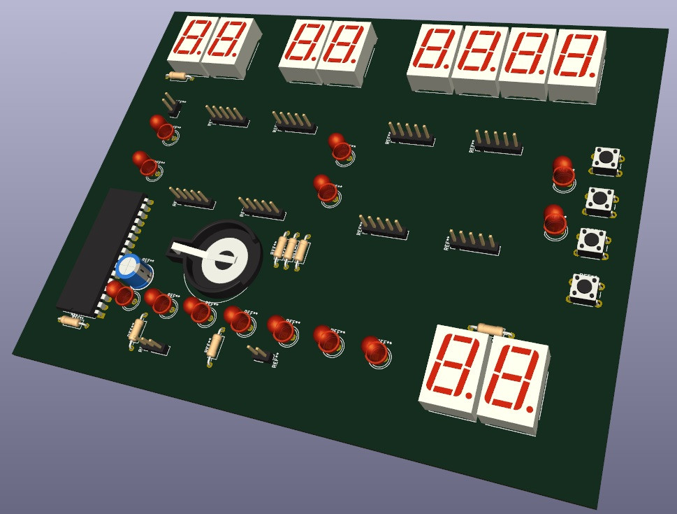
When [Rodrigo Feliciano] realized that the reason his seven-segment LED wall clock wasn’t working was because the original TG1508D5V5 controller was fried, he had a decision to make. He could either chuck the whole thing, or put in the effort to reverse engineer how the displays were driven and replace the dead controller with something a bit more modern. Since you’re reading this post on Hackaday, we bet you can guess which route he decided to take.
If you happen to own the same model of clock as [Rodrigo], then you really lucked out. He’s done a fantastic job documenting how he swapped the original controller out for a Raspberry Pi Pico W, which not only let him bring the clock back to life, but let him add new capabilities such as automatic time setting via Network Time Protocol (NTP).
But even if you don’t have this particular clock there’s probably something you can learn from this project, as it’s a great example of practical reverse engineering. By loading a high-resolution image of the back of the PCB into KiCad, [Rodrigo] was able to place all the components into their correct positions and following traces to see what’s connected to what.
Pretty soon he not only had a 3D model of the clock’s PCB, but a schematic he could use to help wire in the Pi Pico. Admittedly this is a pretty straightforward PCB to try and reverse engineer, but hey, you have to start somewhere.
Over the years we’ve featured many projects which attempt to replicate the feel of physical media when playing music. Usually this involves some kind of token representation of the media, but here’s [Bas] with a different twist (Dutch language, Google Translate link). He’s using the CDs themselves in their cases, identifying them by their barcodes.
At its heart is a Raspberry Pi Pico W and a barcode scanner — after reading the barcode, the Pi calls Discogs to find the tracks, and then uses the Spotify API to find the appropriate links. From there, Home Assistant forwards them along to a smart speaker for playback. As a nice touch, [Bas] designed a 3D printed holder for the electronics which makes the whole thing a bit neater to use.
Bluetooth is a backbone technology for innumerable off-the-shelf and hacker devices. You should know how to work with it – in particular, nowadays you will certainly be working at the Bluetooth GATT (Generic Attribute) layer. This two-part project by [V. Hunter Adams] of Cornell fame spares no detail in making sure you learn Bluetooth GATT for all your hacking needs – not only will you find everything you could want to know, you also get example GATT server and client application codebases to use in your projects, designed to work with the commonly available Pi Pico W!
What’s better than a visual demonstration? The video below shows the GATT server running on a Pico W – handling six different parameters at once. [Hunter] pokes at the server’s characteristics with a smartphone app – sending string data back and forth, switching an LED, and even changing parameters of audio or video color output by the Pico. Flash the server code into your Pico W, play with it, read through it, and follow the tutorial to learn what makes it tick. Continue reading “This Bluetooth GATT Course Is A Must Watch”→
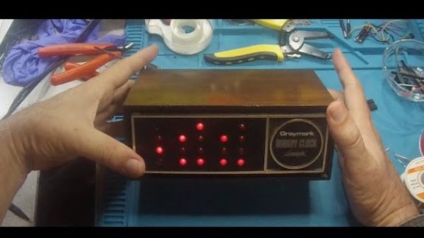
Back in 1978, the world was a bit different. There was no Raspberry Pi, no Internet, and not even an ESP32 to build projects with. And rather than order electronics kits from Tindie or Adafruit, [Dr. Francitosh] selected this binary clock with his mother from a catalog, and made the order via mail. Simpler times. The good Doctor, AKA [Greg Smith], was a young electronics tinkerer, and his mother wanted a good project-in-a-box to show off his skills. Thus, a Greymark Binary Clock was ordered and assembled. Then, sadly, the beloved clock crashed from its proud mantle position, doomed to never to blink or blip again. Or was it? Continue reading “Binary Clock Kit Blips Again”→
Before video games, there were pinball machines. Not that they don’t exist today, but a modern pinball machine will likely have microprocessors and other fancy things that traditional pinball machine designers could never dream of. [Eli] had one of these mechanical machines from 1974 as a kid and, later, encountered a more modern machine with a rudimentary microprocessor and other integrated circuits onboard. One thing this enabled is the ability to remember high scores. But you have to physically look at the machine, and you can only see the top four scores. [Eli] decided to adapt the machine to upload high score data to the Internet, and it is a fun project.
[Eli]’s design goals were to make it automatic and robust. That is, if the network is down or the machine loses power, you shouldn’t lose high score data. In addition, he didn’t want to change the appearance or damage the 40-year-old machine. You can see a video of how it all turned out below.
The Laser Cue machine is one of many built around the “Williams System 7” platform. A 6808 CPU, along with some I/O chips to manage all the lights, sensors, and bells. The game has only 1K of RAM, 12K or ROM, and 128 bytes (no prefix, just bytes) of RAM with battery backup. There was even a common “operating system” called Flipper ROM, and that’s actually documented over on GitHub.
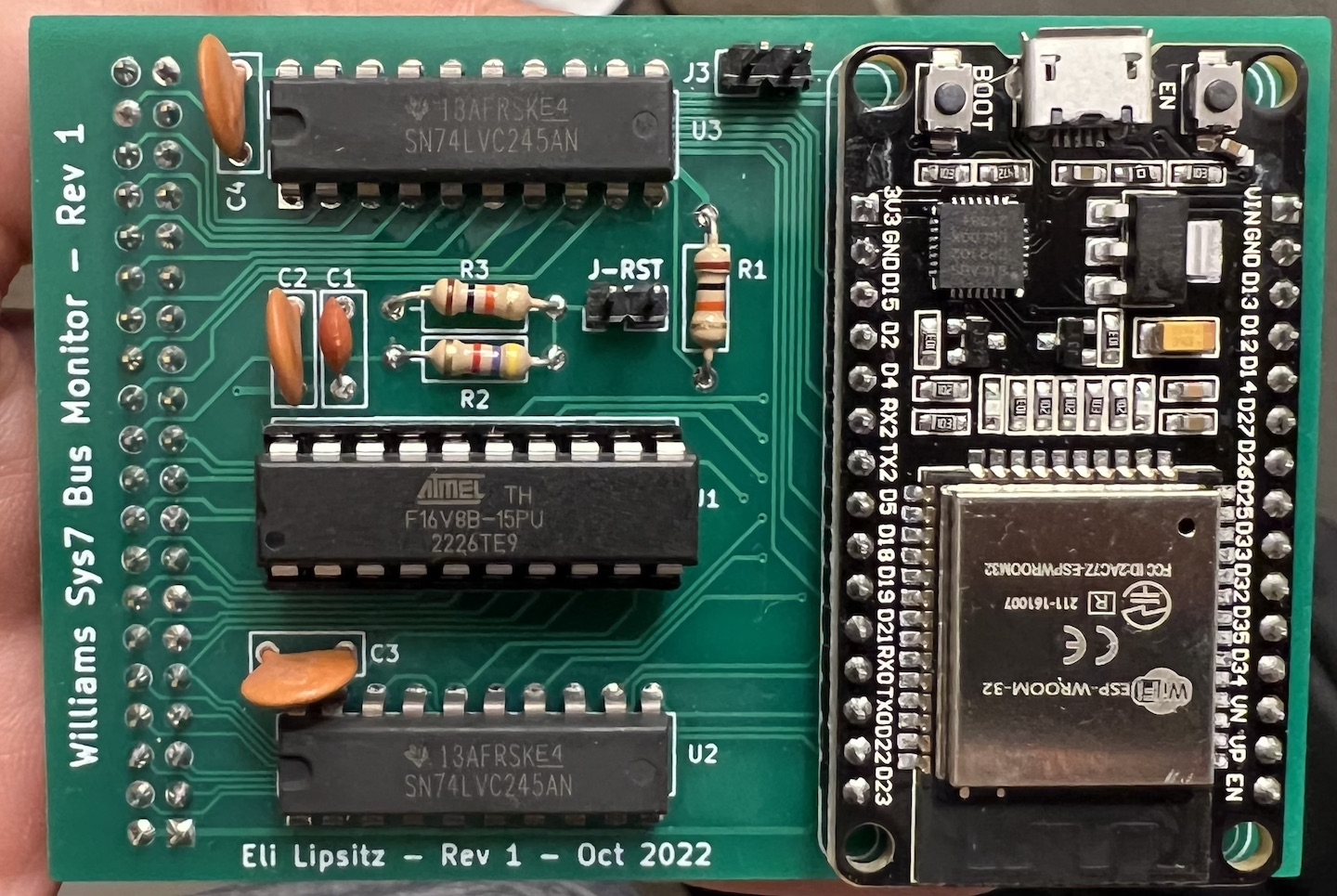
The ESP32 version of the WiFi interface board
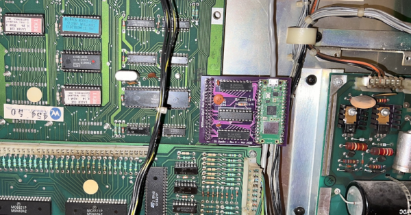
Since the memory for the machine is all in external chips, it was a reasonable idea to replace the CPU with a board that monitored signals on the board. The CPU would plug into this new board, and then a newer microcontroller with an Internet connection could eavesdrop on bus traffic. However, removing the old CPU and jamming pins into the ancient socket was worrisome, so instead, [Eli] elected to tap into a test connector that was already on the board but not plugged into anything.
An ESP32 is more than capable of the speeds, although connecting to 5 V logic was a bit of a problem. The CPU has 5 V tolerant pins, but some of the 25 available pins on the development board either set items on boot or may briefly be outputs and were thus unusable. To reduce the necessary pins, [Eli] decided to do some of the decoding in separate logic. Instead of using TTL chips, he elected to use a programmable logic array.
After that, it seemed it would be straightforward, but there was something preventing the ESP32 from reading each bus cycle. [Eli] never got to the bottom of it but instead switched to the Raspberry Pi Pico W. Using the chip’s special I/O processors made the job easy, and it worked perfectly. The rest of the project was just fit and finish. Be sure to read to the end to find out the lessons learned which might help you on your next similar project.
A modern DIY machine might even have an FPGA inside. Don’t have room for a big full-sized pinball machine? No problem.