[MSylvain59] likes to tear down old surplus, and in the video below, he takes apart a German transceiver known as a U-600M. From the outside, it looks like an unremarkable gray box, especially since it is supposed to work with a remote unit, so there’s very little on the outside other than connectors. Inside, though, there’s plenty to see and even a few surprises.
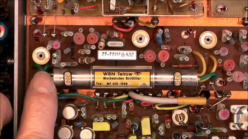
Inside is a neatly built RF circuit with obviously shielded compartments. In addition to a configurable power supply, the radio has modules that allow configuration to different frequencies. One of the odder components is a large metal cylinder marked MF450-1900. This appears to be a mechanical filter. There are also a number of unusual parts like dogbone capacitors and tons of trimmer capacitors.
The plug-in modules are especially dense and interesting. In particular, some of the boards are different from some of the others. It is an interesting design from a time predating broadband digital synthesis techniques.
While this transceiver is stuffed with parts, it probably performs quite well. However, transceivers can be simple. Even more so if you throw in an SDR chip.


Can anyone else smell this?
The fibers from the board, the wax/pcbs, oxidation and whatever the other cancer causing fumes are…
Only since you posted the question.
Absolutely, it smells like every electronics surplus shop from my youth.
Oh most definitely! Ad a pinch of someones stale cigarette smoke for good/bad measure!
Flashback to my teenage years and just doing mostly mechanical repairs for tripped over cords and units hitting the floor.
Yup…
Along with the smell of oxidized silver switch contacts….
Stale rubber wire insulation covered in rotting cotton.
And of course the smell of magic smoke coming from the carbon resisters brown ends black in the middle a small flame. Ahh the sounds of the tech “ahh shhht” my poor dad.
Absolutely! Now I am going to be missing certain shuttered surplus shops for the rest of the day. :-(
the ‘mechanical filter’ is (to me) somewhat evocative of a surface acoustic wave filter. though in this case more like an analog computer made with springs and weights, whereas saw is more like a digital filter where the coefficients and mac is made with spacing and size of the interdigital fingers.
Hi, please have a look at old PAL delay lines used in old TVs
They are akin to primitive memory cells, but on a piezo (?) acoustical principle.
Vy73s
I remember! Useful for separating luma and chroma. I opened one and it was a beautiful structure of a rectangle with two adjacent corners lopped off, with the new edges affixed to a piezo structure. So the signal would be emitted from one and bounce around the edges of the crystal before arriving at the other one. There was also an array of dots deposited on the crystal, ostensibly for attenuating waves not on the desired path.
Did not separate chroma and luma, it delayed the luma to allow the chroma to be ‘decoded’ through additional circuitry and then mix back together in sync.
“German transceiver”
East German transceiver, more specifically.
As a former West German I think that this is not necessarily a bad thing, though.
They had experience building radio equipment and applied it, if they had the materials needed.
Military models like the RFT EKD 500 are sought after to this day.
However, consumer and civil radio products weren’t always good.
Except those made for export, which usually were decent.
The transceivers in GDR police cars were not that great, for example.
Their cars had poor batteries, too. Running at 6V or something.
Hi, please have a look at old PAL delay lines used in old TVs
They are akin to primitive memory cells, but on a piezo (?) acoustical principle.
Vy73s
Why was this posted in wrong spot!? 🥺
Only Trabant had a 6V battery, all other small vehicles ran on 12V. The 600 series was okay for its purpose: 10W FM on 10 crystal-stabilised channels. The 700 series had a PLL and more channels.
Interesting to know, I merely have superficial knowledge here. Thank you! ^^
My father’s 1957 Karmann Cabriolet had a 6V electrical system. While my mother’s 1961 Mercedes-Benz had a 24V one. The Germans were slow to standardize the voltage.
MSylvain has some of the most interesting teardowns.
Can you match a mechanical filter to a mixer / IF amp the same way you would a crystal ladder? For instance could I use an L-network? I have a salvaged one in the junk box but never tried designing for it.
It’s a 1.9khz filter costs 25€ https://www.ebay.de/itm/196718836292?customid=&toolid=10050
Much more likely a 450 KHz filter.
I remembers changing a channel by turning the knob by pliers.
What’s unusual with am EMF? They are the flagship of Russian ham diy and the East German ones are exceptional. They made my EKD500 receiver worth looking all the way in Lithuania to find one. Good buy.