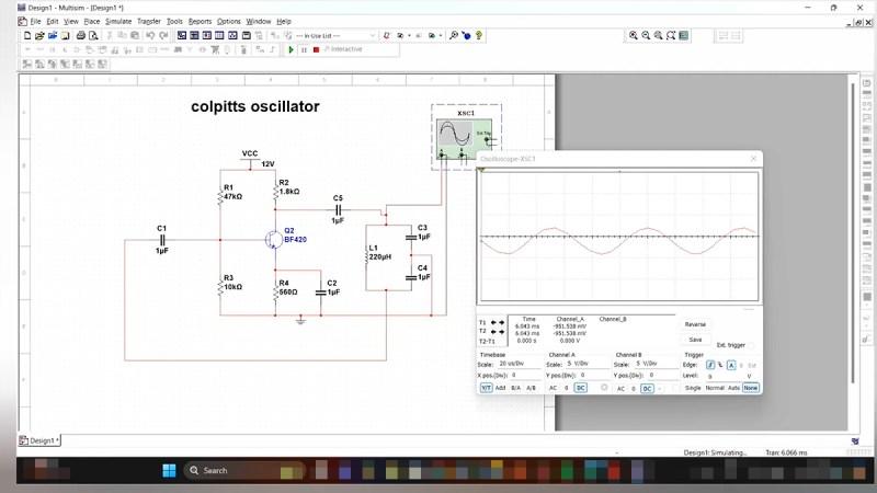
If you’ve ever fumbled through circuit simulation and ended up with a flatline instead of a sine wave, this video from [saisri] might just be the fix. In this walkthrough she demonstrates simulating a Colpitts oscillator using NI Multisim 14.3 – a deceptively simple analog circuit known for generating stable sine waves. Her video not only shows how to place and wire components, but it demonstrates why precision matters, even in virtual space.
You’ll notice the emphasis on wiring accuracy at multi-node junctions, something many tutorials skim over. [saisri] points out that a single misconnected node in Multisim can cause the circuit to output zilch. She guides viewers step-by-step, starting with component selection via the “Place > Components” dialog, through to running the simulation and interpreting the sine wave output on Channel A. The manual included at the end of the video is a neat bonus, bundling theory, waveform visuals, and circuit diagrams into one handy PDF.
If you’re into precision hacking, retro analogue joy, or just love watching a sine wave bloom onscreen, this is worth your time. You can watch the original video here.


Video seems lacking as an instructional video. It’s mostly a recording of her performing the exercise in Multisim, but she doesn’t actually walk you through it nor explain much as she does it.
She says nothing of the theory nor how the circuit works other than showing the manual at the end.
The part numbers of the capacitors placed in the sim don’t match up with the manual. It made the circuit theory in the manual confusing at first.
The video could do without the music. At least it wasn’t too annoying.
hmm. maybe consider a writing position at hackaday: “the sharp eye”. I would welcome such a refreshing view.
These kinds of videos seem to be somewhat common – they might be because of some sort of course requirement to record a learning diary on youtube. The channel is called “saisri study vlogs”.
The only oscillator I have ever built in my life was an astable multi-vibrator. I would love to build a faster oscillator.
I should probably take some time out of my daily life and build all the basic circuits at least once.
you and me both. i even got ahold of a copy of a forest mims transistor book, sigh
theres lots to be learned from the good old two transistor astable. As with a lot of ‘simple’ circuits, theres a lot going on, and components plating multiple roles. Play with. Make an astable with MOSFETs. Measure the gate waveforms, and then compare them to what you see with the BJT version. Or buffer the output of a BJT version with a common emitter stage, and see what happens. See if you an make an H-bridge oscillate. Figure out how to do its with an RL timing element instead of an RC one. Can you make it voltage-controlled? can you make the duty cycle voltage controlled?
Theres a million things you can learn once you start digging deeply into simple circuits.
I recommend checking out the circuit which is a hybrid of Colpitts and Armstrong oscillators. It’s called the ArmPitts topology… 8^]
Boy do I wish people would stop drawing Colpitts oscillators with the “center tapped” capacitor arrangement. It’s not a helpful depiction and makes it seem like something new when the reality is the feedback network is just a ladder filter. It’s an input series cap, a CLC pi network, and an output series cap. If you just think in terms of two-ports, it makes the whole concept generalize much better, and makes analysis easier, and puts the feedback network into a familiar format which is particularly useful for people learning the circuit for the first time. No idea why that particular drawing has stuck around so persistently.
I could be wrong, but I think that came about because sometimes the circuit uses a tapped inductor rather than two capacitors in series.
I have a vague memory that back in the day of tubes it may have been cheaper to tap an inductor than add a capacitor. Also, additional capacitors – especially if they’re physically large and don’t have a very high Q – may result in a circuit that’s less stable and/or more susceptible to electrical noise. So the centre-tapped style of drawing the circuit may be a holdover from those days.
The tapped inductor circuit is a Hartley oscillator. See the wikipedia article.
It seems to me that both Hartley and Colpitts oscillators are typically drawn in the most confusing manner possible, frequently featuring an emitter follower as the active element. That makes the circuit very hard to understand. Sam’s point is valid. For me, the light went on for understanding the Colpitts today, for the first time. (And I’m 76 years old.) Thanks, Sam.
When we were designing a simple 7 MHz direct conversion receiver, we used a Colpitts oscillator. We built it in LTSpice, really just to have a good printable document. I was astronished when the oscillator fired up in the simulator, and the whole receiver started to work IN THE SIMULATOR! We could put an RF signal at the input and watch an AF signal emerge at the output. It was really pretty neat. You can find the LTSpice file in this site: https://hackaday.io/project/190327-high-schoolers-build-a-radio-receiver. We recently asked people around the world to built the receiver. 56 of them have successfully did so: https://soldersmoke.blogspot.com/search/label/DC%20RX%20Hall%20of%20Fame Saisri’s Colpitts topology is a bit different from what we are used to, but her simulator shows that it works. I urge her to go into our Discord server and then build the receiver that used the same kind of oscillator that she has simulated. Bill
If you are the guy that made the receivers and the videos I want to sincerely thank you for making not only an awesome accessible project but for teaching what every single component does and why and all that. Honestly one of the absolute best series for a ham delving into home brew. Thanks again.
.
And we’re all waiting for the transmitter!
73
Thanks — the videos were all made by Dean KK4DAS. We are both on the SolderSmoke podcast.
The connection is everything!