In the early years of electrification, when electricity was beginning to shape the modern world, this new technology was being put to use in many more places than turning motors and providing lighting. Some things we can see as obvious missteps like electrified corsets marketed as health tonics or x-ray treatments for eye strain, but others ended up being fascinating bits of technology with interesting uses, many of which have been largely forgotten since. This 100-year-old musical instrument is squarely in the latter category, and this build brings the sound of it back to life.
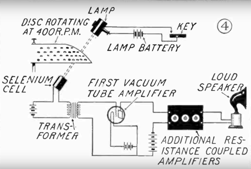
The instrument was called the Luminaphone and was originally built by [Harry Grindell Matthews]. Of course, this was an age before transistors and many other things we take for grated, so it has some quirks that we might not otherwise expect from a musical instrument. The device generated sound by shining a series of lights through a perforated rotating disc at a selenium cell. The selenium cell was an early photoresistor, generating current corresponding to the amount of light falling on it. A keyboard activated different lights, shining on areas of the disc with different numbers of holes, causing differing sounds to be produced by the instrument.
The recreation was built by [Nick Bild] and uses a laser diode as a stand-in for the rotating disc, but since it can be modulated in a similar way the idea is that the photodiode used as a receiver would generate a similar sound. The recreation sounds a bit like a video game from the 8-bit era, but with no recordings or original Luminaphones surviving to the present day we may never know how accurate it is. There are some other electronic instruments still around today, though, and plenty of ways of DIY-ing their sound like this project which recreates the tonewheels of the classic Hammond organ.


and don’t forget the Optigan, the organ using an exchangable optical disk to generate sound. that is a direct descendant of this device.
My parents bought me one in the late 70s. Loved it! Wish I still had it.
A selenium cell responds much more slowly than a photodiode, so I suspect the original sound was quite different (probably closer to a sine than a square wave). Also, since the original docs show a colander-like “disk”, so it seems that there were multiple light paths, possibly further altering the sound.
Makes sense. How about an LDR instead of a photodiode?
It’s slower, I think. My next idea as a replacement is a solar cell as sensor.
Yep, an old-school CdS LDR should do the trick.
Banned because of RoHS.
The technical and mechanical limitations of the instrument would have produced an entirely different sound compared to blasting a square wave out from an Arduino.
Keying the lightbulbs on and off would, for example, produce a distinct attack and release function. How they managed to have multiple keys with apparently not enough hole patterns or lamps for each key is also a mystery – which suggests that they summed up different patterns to achieve the right number of pulses per second but not necessarily equally spaced – which would also have contributed to an unique sound.
I completely agree with you. They should just recreate it faithfully (okay, with LEDs). Sounds like a nice project.
I think you missed the point. LEDs are (nearly) instant-on and instant-off, depending on the specific LED and circuit design of course, but even worst case “slow” phosphor coated types (like white LED) have times measured in like… 100 nanoseconds. Modern incandescent bulbs have a MUCH slower turn on / turn off time, depending on the filament. Keeping wattage the same, a lower voltage bulb will be slower than a higher voltage one. Ballpark figures a 220V 50W might reach full brightness in perhaps 25ms, while a 12V 50W one might take several hundred ms. Changing the wattage and with the same voltage does the same – a 220V 500W takes over a second to reach full brightness!
And another complication is that the response time of a selenium cell is also much slower than a photodiode, a fast one perhaps in the 0.1ms time frame, I’m not exactly sure. I know they were used as the sensor in very early optical soundtrack for playing back sound from film projection, so those designs could certainly handle something in the khz range. But there were other types which were much slower, maybe more like 1-10ms. This is another form of analog filtering that would affect the final sound.
The LED and photodiode musical instrument is certainly very interesting, but there is absolutely no way it sounds anywhere near what the original instrument sounded like.
You’re right. Perhaps emulate the on/off time with a RC circuit? Would be worth testing – together with a spinning disk. It seems, the next project is in the queue ;-)
My feeling is that the end waveform resembles a sine wave, but with flattened peaks. And the on/off characteristic of the lamps and the slowness of the selenium detector would give a mellow attack and decay. So I think that the sound would be quite mellow.
Maybe he will make the real thing, and we would get to hear the actual sound. :) I guess the only question is if Nick will think it’s worth the effort to build it.
It would also include light leaking in through adjacent rows of holes, so each key would be modulated by its neighbors, plus whatever ambient light you have. It might be quite rich in harmonics and beat tones.
There definitely are enough lamps and hole patters for each key to have its own. Just eyeballing it I’d say he’s got a three octave range with a lamp for each note and a corresponding hole pattern.
Okay, cool concept, but the I would not use the word “recreation”, as this is a bit overstretched.
It’s like making spaghetti bolognese, but using shoe laces instead of pasta, red paint for the tomato sauce and rubber balls for the meat. Selenium cells are slow, real slow, this would affect the sound greatly, lightbulbs are slow, this would affect the sound envelope greatly. I hate to say it, but perhaps using a 555…
I wish he would have built it like the original. I have a feeling it would sound a lot different. This just sounds like a square wave that’s been slightly low pass filtered. Using a 1920’s horn speaker would probably make it sound a lot different too.
I wonder why the disc should be rotating at 400 rpm instead of 440 rpm. It must be a clue as to the spacing of the dots.
Small calculation. Say that the circumference of the circle with holes on the disc is exactly 100cm (disc with a diameter of 31.831cm, which seems reasonable, looking at the pictures). At 400 rpm that would be 400 times 100cm per minute (40,000cm per minute), or 666.67cm per second.
If I’m deducing and calculating correctly, to get a 400Hz tone, you would want to have 400 holes in those 666.67cm, or one hole every 1.16667cm.
For a 440Hz tone, that would be 666.67/440 = 1.5cm between each hole. That’s a nice number. Although well, the placements of the holes is ‘analog’, so a hole every 1.666666667cm wouldn’t be much harder.
If I look at the photograph at 1:13, I see two things: 1) the holes on the left disc form a kind of spiral pattern, 2) the distances between the holes seem quite close to 1.5cm.
I would think that the size of the holes also will matter. Not for the amplitude, but for the shape of the waveform.
So, now somebody should just make the real thing ;). Maybe the disc could be printed with a 3D printer? But to be more historically accurate, maybe you could form a metal disc in the more or less required umbrella shape and then use a 3D CNC machine to drill all the holes?
I would be willing to bet that it was 400 rpm because he used an AC motor and a gear reduction that was available.
I will not take you on that bet. Sounds just as plausible. ;)
If you’re running at 400 RPM you get closer to the correct frequencies with an integer number of holes around the circle.
66 holes = 440 Hz (A)
62 holes = 413 Hz (315 Hz G#)
59 holes = 393 Hz (392 Hz G)
56 holes = 373 Hz (370 Hz F#)
and so-on.
Meanwhile, if you start at 440 RPM you get
60 holes = 440 Hz (A)
57 holes = 418 Hz (315 Hz G#)
54 holes = 396 Hz (392 Hz G)
51 holes = 374 Hz (370 Hz F#)
You can’t hit the notes exactly – there’s always going to be some that are off by a little bit because the ratio between each note is an irrational number. Running the disc slower means you get more divisions per rotation, which gets you closer to the desired frequencies., but if you run it too slow then the holes will be too tightly packed and there’s less separation between light and dark for the sensor.
Typo: G# is 415 Hz
Or, you could have multiple disks at multiple speeds connected by belts. Belts and pulleys are great for irrational ratios if you will pardon the pun.
Then you need to decide whether you want just or even tempered scales.
The Hammond organ did it with gears. Obviously not irrational ratios, but close enough.
Cool stuff. Except the synthol, not cool.
“photoresistor, generating current corresponding to the amount of light falling on it” that would be a resistogen or diodiotor, not a resistor.
Note that selenium rectifiers could be used if they were not painted. These plates are not for cooling. The device requires large active surface areas. They were in everything, TV, radio, any device that needed DC, for decades. They have a peculiar smell. https://theodoregray.com/periodictable/Samples/034.2/index.s15.html
I have to admit I love the reverse taking modern music and recreating it with the pinicle of 1930’s technology (That is only 95 years ago)
e.g.
https://youtu.be/cHLbaOLWjpc
I knew which video that’d be before I even clicked on it. Orkestra Obsolete, with their spine-tingling 1930s rendition of New Order’s Blue Monday. Good stuff!
No mention of the Compton organ with it’s “film sound track” discs each one the same for 12 spun by a belt and 12 different pulleys. Essentially the first sampled sound musical instrument, flute diapason string etc. Keys opened gates for envelope control with no clicks which was a problem for everyone else till Baldwin’s pressure resistance keying.
I don’t know who to reply to here about the modern electronics having a much faster, switching time and making a square wave, but in this case it doesn’t matter
I would like to point out that the optical part of it could easily make up for that. Depending on on a lot of hand waving, the distribution of light through an aperture tends to be pretty Gaussian. The reason imaging optics are expensive is all about making it less Gaussian.
Anyway, a line through bunch of Gaussian spots is pretty much a sine wave. A shaped mask on the light sensing device could make as much difference aa electrically filtering the signal.
What shocks me most is that the original parts are just bog standard parts, that used to be widely available just 20 years ago.
With exception of the silenium cell, of course.
Yet in 2025, people don’t even have access to a simple little lightbulb (incandescent lamp) anymore.
That’s depressing. It’s as if resistors or capacitors are nolonger available.
Or a mechanical switch. Or a 3,5mm jack etc.
Techically we do – because they haven’t managed to make LEDs that can operate at 300 C – which means we can still buy 15 and 40 Watt “appliance lamps”.
The irony is that these are less efficient and dimmer than the equivalent halogen bulbs that were banned because of efficiency regulations. Two 40 Watt fridge bulbs in a Y splitter will give the same light as the old 60 Watt bulb did.
Nice. A bit of light music.
Early photographic light meters used selenium cells; these meters were self-contained and didn’t require batteries.
It’s a Mr. Quintron Drum Buddy!!! https://www.drumbuddy.com/
Just a thought, maybe someone can make the rotating slotted drums by 3D printing them?
A lot of modern computational power could be brought into play designing such instruments, and ai can use feedback from any design attempts to change/improve/tune the next 3D printout.
Reminds me of the Electric Fan Harp that the band ELECTRONICOS FANTASTICOS uses.
https://youtu.be/QJavHc48iZU