Many people who get analog electronics still struggle a bit to design oscillators. Even common simulators often need a trick to simulate some oscillating circuits. The Barkhausen criteria state that for stable oscillation, the loop gain must be one, and the phase shift around the feedback loop must be a multiple of 360 degrees. [All Electronics Channel] provides a thorough exploration of oscillators and, specifically, negative resistance, which is punctuated by practical measurements using a VNA. Check it out in the video below.
The video does have a little math and even mentions differential equations, but don’t worry. He points out that the universe solves the equation for you.
In an LC circuit, you can consider the losses in the circuit as a resistor. That makes sense. No component is perfect. But if you could provide a negative resistance, it would cancel out the parasitic resistance. With no loss, the inductor and capacitor will go back and forth, electrically, much like a pendulum.
So, how do you get a negative resistance? You’ll need an active device. He presents some example oscillator architectures and explains how they generate negative resistances.
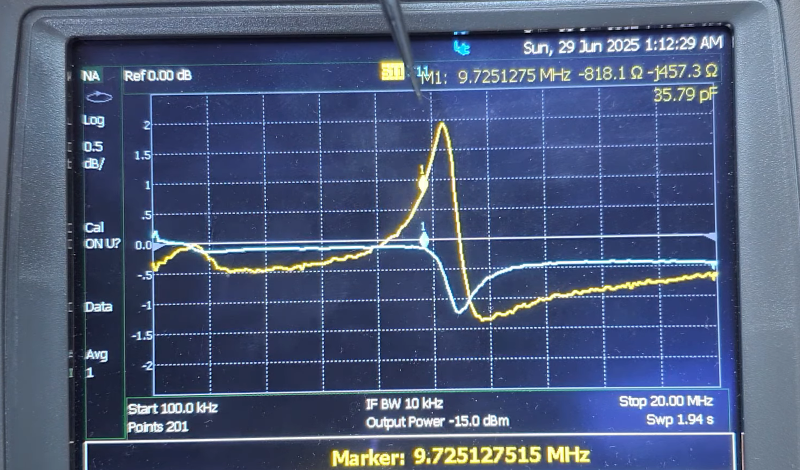
Crystals are a great thing to look at with a VNA. That used to be a high-dollar piece of test gear, but not anymore.


Oscillators are easier to make when you’re not trying to make one.
More true than I’d like to admit.
He really hammers down the principles behind negative resistance. The video is however rather thin on the details of the presented oscillator circuit. He went to the effort of building a prototype of it, but he doesn’t demonstrate that it’s actually oscillating.
Likely because it is entirely for demonstration, but I agree that would round it out. Otherwise this is really good, I’m not sure I remember seeing the concept directly addressed in detail like this.
Electric arcs have negative resistance.
Yes, and if your vacuum breaker loses it’s vacuum you can have some unhappy results – I saw the consequrnces on a 6.6kV motor that was driven via a captive transformer, much over voltage occured.