Over on his YouTube channel [Tom Stanton] shows us how to build a Stirling Engine for a bike.
A Stirling Engine is a heat engine, powered by the expansion and contraction of a working fluid (such as air) which is heated and cooled in a cycle. In the video [Tom] begins by demonstrating the Stirling Engine with some model engines and explains the role of the displacer piston. His target power output for his bike engine is 150 watts (about 0.2 horsepower) which is enough power to cycle at about 15 mph (about 24 km/h). After considering a CPU heatsink as the cooling system he decided on water cooling instead.
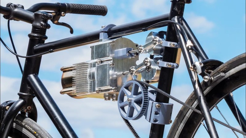
[Tom] goes on to 3D print and machine various parts for his bike engine. He uses myriad materials including aluminum and Teflon. He isn’t yet comfortable machining steel, so he had the steel part he needed for handling the hot end of the engine manufactured by a third party.
[Tom] explains that when he started the project he had intended to make a steam engine. But after some preliminary research he discovered that a Stirling Engine was a better choice, particularly they are quieter, more efficient, and safer. After a number of false starts and various adjustments he manages to get his engine to run, which is pretty awesome. Standby for part two to see the bike in action!
We have covered the Stirling Engine here on Hackaday many times before. You might like to read about how to create one with minimal parts or how to make one from expedient materials.


“Includes paid promotion”
Also- I can’t fathom how this works. Stirling engines function on a heat differential. I skimmed the video and cannot see where that heat differential is generated. In models a candle or alcohol burner supplies the “hot end” and this write up says it’s water cooled (??).
Stirling powered watercraft I’ve seen written up were heat-fired. Even the coffee cup varieties use the heat from the coffee.
There is not much I can imagine that carrying around a cryo cooler or something is remotely close to providing useful work.
He heats the hot end with a blow torch.
Well, that is pretty much as disappointing as @craig expected.
But I just had a wired thought: What if one uses a heatpump to power a sterling engine?
Basically efficiency comparison
Li* power -> e-motor
VS.
Li* power -> heatpump -> sterling motor
I assume sterling motors have a lot worse efficiency but whatever (and they’re heatpumps too).
Maybe I’m too tired but the idea of
A heat engine and a heat pump are reverse effects of each other.
Carnot’s theory says the coefficient of power of the ideal heat pump would be exactly inverse of the efficiency of the corresponding heat engine running at the same temperature difference, so for a CoP of 3/1 you would get a thermal efficiency of 1/3.
In other words, it just cancels out.
Only in a closed system. In the atmosphere, if you can cool your initial gas to (much) lower than the ambient temperature, then you can suck then ambient energy (in a way, you’ll be cooling the air around you), to reheat the gas ambient temperature. However, compared to a classical heat pump, your bike will have moved meanwhile, so the ambient air is now hotter than the previous cycle (since you’ve left the cold air behind). I suspect that this could give a (very) small efficiency advantage to the heatpump compared to the heat engine. I doubt it could be enough to counter act the usual loss of such system however.
That doesn’t make any difference to the case.
Using the ambient air as you suggested, is the exact same thing except the intake side of your heat pump is allowed to run colder, which reduces its efficacy, and the exhaust side of the heat engine is allowed to run hotter, which reduces its efficiency.
For optimum performance, you would want to run the cold air coming off the heat pump to cool the heat engine directly, but this is just looping the two devices together and you simply get a 1:1 ratio between the energy in and out. For any practical scenario that introduces non-ideal conditions like using the ambient air as a heat reservoir, you’re going to get less than 100% efficiency.
In the ideal situation, your heat pump would see no drop in temperature at the intake when it runs, because you’re pushing so much air through the radiator that the temperature simply cannot drop no matter how much heat you’re pulling out of it. This maximizes the amount of heat you can pump with a given amount of work you put in.
Likewise for the heat engine. It should be cooled so well that the exhaust temperature does not rise above the ambient temperature. This maintains the maximum temperature difference across the engine, and therefore maximizes the work you can extract out of the heat you put through the engine.
With the heat pump intake and the heat engine exhaust forced to remain at the same ambient temperature, it doesn’t matter if the two devices are operating in free air or whether you’ve hooked them together directly end to end.
Or, if it’s easier to imagine using an analog:
Imagine you have a big lake – that’s your ambient air – and you have a pump that lifts the water from the lake up a tall tower. Then from the tower it drops down through a turbine that runs the pump and lets the water back into the lake. The height represents the temperature of the system in this analog.
Now it’s obvious that this is no perpetual motion engine and there’s no benefit in using it because it takes just as much energy to pump the water up as you can ever hope to gain back from it. It can only return your energy back, or less.
The only way you could do better is if the water you pump comes from some source that is higher than the lake. You gain energy from the difference in height or temperature from input to output, and it doesn’t matter what you do in between. If the difference is in the opposite direction, then you’re pumping heat from a lower input to a higher output and losing energy instead of capturing it.
I too had the idea that maybe you could use the heat pump to utilize some low grade heat source that is slightly above ambient temperature, like heat from sewer water, but then I realized that once you run the math, the overall efficiency of the system is going to be dictated directly by the temperature difference between the two reservoirs and nothing you can do with the heat pump makes any difference to it.
What I think could be interesting is using the details from NightHawkInLight’s most recent video to use the sun as the heat source, granted, then it would only run in the day, at certain times, when you have a reasonable amount of lights
You could even apply one of his other recent videos and use “passive sky cooling” to increase the temperature differential.
I once thought about a system with compressor, then using the heat for the hot side of a stirling engine, then decompressing in a turbine and using the cold outlet of this on the cold side of the stirling engine. The idea was to use the heat difference and then reclaim the work used to compress the medium.
After I learned how to do integrals at school, it turned out the loss of heat on the hot side reduced the reclaimable work in the turbine exactly by the amount gainable with a carnot cycle in place of the stirling engine, because the cooling reduces the volume available for the turbine (pV/t=const.). It did not matter wether to use the heat exchangers in parallel or antiparallel configuration: different integrals, same result.
(Parallel meaning “use the hot end of the hot side heat exchanger with the hot end of the cold side heat exchanger”, antiparallel meaning “use the hot end of the hot side heat exchanger with the cold end of the cold side heat exchanger”; you have to use the carnot cycle with infinitesimal small heat bits, otherwise you lose efficiency)
Funny how that works.
No lies detected.
“I skimmed the video …”
Funny how reading comprehension works.
Or in your language, “I didn’t read the comment but had my own sarcastic comment anyway”
The project is not completed. He mentions towards the end he still needs to build “a proper burner” for it.
The hot end is the thick steel cover over the cylinder. He does a couple demonstrations where he loads up the cover with heat from a torch and it continues running for a couple minutes after he removes the torch.
Around 10m mark – https://youtu.be/zB3lrLjqIh4?si=0w6XXvWJ6kR7u54W&t=607
Around 15m mark – https://youtu.be/zB3lrLjqIh4?si=ADQV1votXA20ORY0&t=921
Skipping to the last minute or so of the video, he’s test-firing it by hitting it with a propane torch, and then mentions “I also still need to build a proper burner”.
It also doesn’t actually spin the bike wheel in this video other than a few weak turns on a test stand, so it’s very much a work in progress.
Having built a multi-piston, pressurised, alpha Stirling engine with a 3kw custom made electrically fed hot end and dyno, about 50x larger than that, my first thought when I saw it and his target power was “good luck”. I got about 40W at 4 bar with 2x55mm pistons at each temp and a large multilayer steel regenerator.
I usually find Stanton’s stuff to be at least interesting but during this entire video I spent more time wondering if he was capable of testing the engine before he bothered with hooking it up to the bike, and the answer was absolutely not. I was very disappointed to see this because this behavior has quite often lead to clickbaiting.
Let me clarify. I know Stanton is capable of testing the engine but him not doing so is what someone who wants more clicks will do so that he can get more engagement, etc. and more often than not the inevitable path taken after that will be clickbaiting. I’ve seen it happen enough to recognize it at this stage of progress.
I had assumed that he wanted the rear wheel to act as a flywheel. Of course, he later added a discrete flywheel as part of his experiments, so…
You could be right about the clickbaiting though. Still, I enjoyed the video, I’ve enjoyed plenty of his videos in the past.
I’ve long been interested in this and found a few companies have opened and closed .. see this link and tell me your thoughts https://studylib.net/doc/18311245/10-kw-peak-power-chp-multi-fuel-stirling-generator
I’m sorry but I’m going to be a real partypooper here. I relly dislike negative commenting, but I HAD need to think twice before posting whatever youtube suggest they watch.
This is completely bogus/futile. I’ve built several Stirling engines in my days. To get any useful power out of them you need to enclose the whole engine in a gas tight shell, and pressurize that (usually with helium at about 10 bar). Just making a Sirling engine run RELIABLE and CONTINIUOSLY is hard. Real hard. Making it produce useful output power is even harder. It requires precision machining and very careful selection of materials. This is NOT something you will be able to 3D print out of plastic. I’m sorry, but this guy will not be able to produce a Stirling powered bicycle. Maaaybe ad money for himself if people keep clicking these kind of videos…
If one wants to build a Stirling engine I’d suggest starting with a model and just work on that until it runs every time it’s started, until the fuel runs out. Then, evaluate that project and perhaps take the idea further.
Also, a Stirling engine should have a regenerator to be called “Stirling engine”. There are many kinds of “hot air engines”…
Pretty much this. For all that I’ve learned of Stirlings, you need the working fluid (gas) to be pressurized in order to increase the pressure swing and carry more heat, therefore generate more power. At atmospheric pressures, the engine would turn out absolutely massive for any appreciable amount of power.
With the gas inside the engine being pressurized, the gas outside needs to be pressurized too or the piston would just get stuck at one end – hence the gas tight shell. Some designs try to use springs for the same point, but with millions and millions of load cycles at very high stress levels they tend to fatigue and break. However, this limitation only applies to single piston Stirling engines.
The ASE project Mod II stirling car engine used hydrogen as the working fluid, pressurized up to 100 bars and managed just about 83 HP peak power output. As far as I can tell, they managed to do away with the pressurized shell design by having two pistons working in opposite strokes pushing against each other, so it was the difference in pressure between the cylinders that did the work. That however meant that the piston seals had to contain the full 100 bars of pressure against the atmosphere and hydrogen would gradually leak into the crank case.
Leaking hydrogen however was not a problem. The way you throttle the Mod II engine is by changing the density of the gas in the system by increasing or decreasing the pressure. When you press the gas pedal, it opens a valve to a pump which squeezes more hydrogen into the cylinders, and when you let go of the gas pedal the gas leaks back into a reservoir. This way the hydrogen that did leak out of the engine was being replaced and you only had to fill up the reservoir every once in a while.
The engine itself turns the compressor, so throttling up too quickly chokes the engine. The throttle response is “glacial” but still faster than trying to adjust the burner for the same point. The other way of throttling a Stirling engine is by opening a valve into a side reservoir, which eats up the pressure swing and wastes the energy, so you’re basically running the burner at full power all the time and simply letting the extra heat blow out of the radiators. That’s obviously not good for fuel economy, which is why they had to go with the more complicated pressure pump system.
The difficulty of making the engine run in the first place is exactly because of the need to throttle the amount of heat that flows through it. The density of the working fluid, its heat capacity, and the cycling speed and load on the engine must be matched to the burner’s heat output or else the engine will run very inefficiently or stall.
https://pubdocserve.sandia.gov/sand_doc/CSP/external/CSP-0988.pdf
The ASE report detailing how the engine operates. They were getting 38% efficiency and 7.8 liters per 100 km which is OK for 1980’s cars, but the power output was a bit wheezy.
Main disadvantage of stirling engines vs. internal combustion engines is that you have to put all the energy through heat exchangers (one for input, one for extracting the waste heat), which tend to be bulky and limit the temperature available for the working process. On ICEs you generate the heat inside the cylinder, and since the expansion immediately takes energy out you can use temperatures no heat exchanger can withstand, increasing efficiency. Waste heat is mainly ejected with the exhaust gas stream, so again no heat exchanger (the coolers on cars are only for the heat that leaves the process sideways).
Pretty interesting. As many of us hobbyists around here have probably built one and then thought “great if I need to move a feather 3 inches”, this is a fairly complicated thing with a simple principle. I honestly thought the stirling would be powering a generator to charge a battery that fed an electric motor of some sort. Kudos for trying to go the full route.
Will this appear on the next fast and furious movie which will be super good