In his regular browsing on AliExpress, [Ben Jeffrey] came across something he didn’t understand—a $5 fiber optic to RF cable TV adapter. It was excessively cheap, and even more mysteriously, this thing didn’t even need power. He had to know how it worked, so he bought one and got down to tinkering with it.

[Ben] needed some hardware to test the device with, so he spent $77 on a RF-to-fiber converter and a cheap composite-to-RF modulator so he could test the $5 fiber-to-RF part. A grand expenditure to explore a $5 device, but a necessary sacrifice for the investigation. Once [Ben] hooked up a fiber optic signal to the converter, he was amazed to see it doing its job properly. It was converting the incoming video stream to RF, and it could readily be tuned in on a TV, where the video appeared clean and true.
It was disassembly that showed how simple these devices really are. Because they’re one-way converters, they simply need to convert a changing light signal into an RF signal. Inside the adapter is a photodiode which picks up the incoming light, and with the aid of a few passives, the current it generates from that light becomes the RF signal fed into the TV. There’s no need for a separate power source—the photodiode effectively works like a solar panel, getting the power from the incoming light itself. The part is ultimately cheap for one reason—there just isn’t that much to it!
It’s a neat look at something you might suspect is complex, but is actually very simple. We’ve explored other weird TV tech before, too, like the way Rediffusion used telephone lines to deliver video content. Video after the break.


Is RF TV over fiber a standard thing to begin with? As I’m struggling to see why would anyone need this adapter in the first place.
It is! It’s more commonly known as RFoG (pronounced ARE-FOG) for RF over Glass. Cable companies will deploy FTTP but their entire business model and backend systems are built around HFC plants and DOCSIS. Instead of running GPON or XGS-PON on the fiber which would require changes to the headend and billing systems, they’ll run DOCSIS on RFoG over the FTTP network.
The wikipedia article is pretty good: https://en.wikipedia.org/wiki/Radio_frequency_over_glass
IMHO, they should just bite the bullet, update the system, and run XGS-PON on those networks but that requires CAPEX and expertise they may not have.
As for this adapter, you’d be amazed at what gets deployed in Chinese apartment buildings to get signals where they need to be on whatever infrastructure may exist in the building. It’s also likely this adapter could co-exist with GPON or XGSPON on the same fiber as long as the photodiode filtered out the non-TV wavelengths.
Several of the big MSOs like Comcast and Charter do run real PON too. They do various flavors of EPON instead of GPON/ITU-derivatives though.
And since they’re so married to DOCSIS they run a provisioning emulation layer on top called DPoE. But that’s just for provisioning and OAM stuff, it’s just EPON under the hood.
Yep, I worked at one that did it with
Evertz gear (over a decade ago), used to convert satellite signal to digital, then back to RF at the NVHE
The basic tech behind it is RF over Fiber, or RFoF. When it’s cheap and bad it’s RFoG, but the basics behind it are a laser you modulate and a photodiode at the other end.
Over long distances, RF loss over coax is much higher than optical loss over fiber. Additionally the RF loss is frequency dependent, whereas the fiber loss is flat with frequency.
RFoF is used in lots of places where the antenna is far from the receiver (antenna remoting). There are other benefits too.
Biggest downside to this is that it is exceptionally noisy and has low dynamic range. You usually need a 20-30 dB amp at the source to get even close to a 0 dB noise figure.
In cable cases though it works because the original signal is huge and so the noise doesn’t matter much.
How do you explain it working with just the antenna then?
Same answer.
(cheap and bad isn’t fair, RFoG is really a name for buckets of passive optical stuff in networking. Bad joke.)
Another advantage is that frequencies on these optical cables don’t interfere with amateur radio band.
Here in Germany, for example, cable TV used to interfere with 2m band. More precisely it was cable TV’s special channel S6 (145,750 MHz).
And it’s especially annoying if an ham radio repeater is on that frequency.
Optical connections may have their disadvantages, but they do at least don’t leak RF.
This is replacing the transport rather than the broadcast: if your coax is leaking RF that bad, fix the coax.
That recommendation makes no sense to me, except if it was supposed to “trigger” me and make me upset.
If so, it failed. I’m perfectly calm and relaxed, also because it’s not “my” problem.
It simply came to mind, because I was listening to hams on local FM repeater on my scanner once and heard the discussion about it.
Anywwy. The problem with the interference isn’t on the amateurs’ side, but that cable TV infrastructure uses that frequency and
that coaxial cables on the streets and in the apartment buildings
are badly maintenainenced or have poor shielding.
If buildings had used fiber connections like shown in the video, then the noise floor would be lower and the S6 channel problem wouldn’t exist anymore.
But that being said, this was from years ago when analog cable TV still existed.
It could be that the S6 issue has solved itself. vy73 and have a nice weekend.
If there’s a company with broken coax bad enough to leak, I doubt they’d have the expertise to deploy this.
Why would it be noisy? Light should have LESS noise.
I would think if there is so much noise it’s the amplifier that drives the LASER, but then you can just use a better amp surely. Same for dynamic range, good amp and suitable LASER should do the trick, although high quality LASERS can get expensive I suppose.
And to Volt-K: I can see tons of reason, like the damn issues with ground on antenna systems, especially cable (I’ve measured hundreds of volts on cable’s ground compared to earth ground, and I’ve seen cable installers yelp from being zapped). And how about lightning? Seems having fiber in between would be a good protection from places that need to be extra safe. And it would be good against EMP’s too I would think.
Anything generates noise – the effective resistance of the photodiode is extremely high, hence extremely high noise relative to thermal.
The noise figure of a directly modulated RFoF link with no preamp is like 20 dB, whereas you can get RF amps that add so little noise it’s better measured in kelvin.
And those are the good ones: crappy ones have a noise figure as high as 40 dB.
Going by you the world will never get fiber communication.
But uhm…
Being noisy isn’t a deal breaker, it’s just a downside. You can work around it for most situations. You just need signal.
These aren’t opinions, they’re just facts. I’ve tested and characterized buckets of RFoF and helped design custom ones.
The power from fiber is interesting enough.
I went down that rabbit hole a few months back. There are some industrial devices for it that are expensive and produce little power, but they apparently do have a niche.
https://www.fiberopticlink.com/product/fiber-optic-isolation-systems/power-solutions-for-fiber-optic-isolation-systems/power-over-fiber-system-pof/
Nope,
the TV supplies power over Coax. Just like it would do for an “active antenna” (an antenna with an embedded signal booster).
The article is simply wrong. The miniscule nanoWatts that arrive via the light on the Fiber are not enough to do anything with passive components.
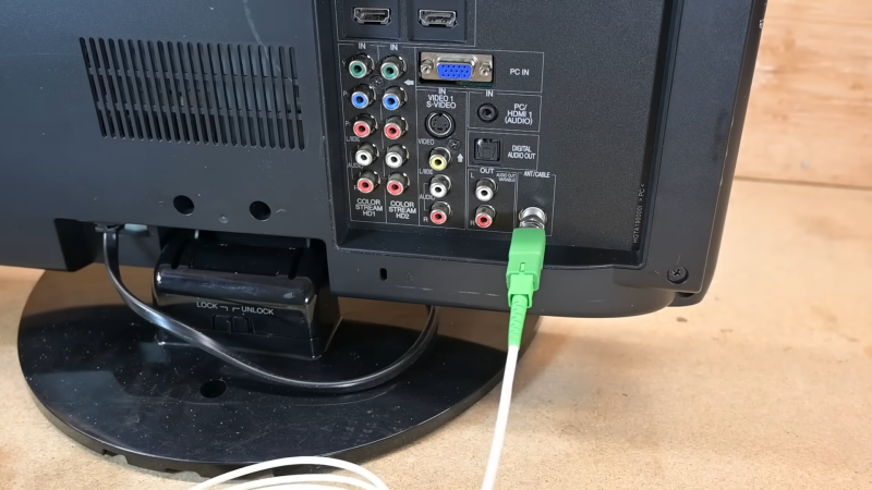
If you look at the image above, you can clearly see 3 pins on the optical receiver. That is a PhotoTransistor. You need enough power for the Bias Current. That is supplied via the Coax input on the TV. NanoWatts are not enough for it.
In the end of video, though, the guy unplugged the receiver side,
held it in close approximity to the RF connector and the image remained (albeit noisy)..
Also, generally speaking, many phototransistors can be run in diode “mode”. With varying results, I do admit.
Are you aware of “Optomos” solid state relays? These have a LED, a string of photocells and two back to back connected MOSfets. When the LED shines it’s light on the photo cells, it generates a gate voltage for the FET’s.
That’s essentially how undersea (or any super long distance) fibre cables work. They use doped fibre which passes the signal as normal but are also injected with a different light frequency which ‘powers’ the doping elements causing them to amplify the actual signal.
That is a very special application for undersea cables. Why not use the DC power delivered from the TV that is essentially already there on almost all TV sets?
Why not use cheap stuff with easy solutions?
Why go some complicated nanowatt to power to rf stuff?
“All TV sets”. US American TVs, maybe. Those with the weird F connector that is meant to be used
with these thin, white cables that connect to satellite receivers
(which have powered connectors, indeed) and LNBs of parabolic mirrors.
Over here in my country, within Europe, we have Belling-Lee connectors for terrestrial TV, VCRs/old game consoles and cable TV.
https://en.wikipedia.org/wiki/Belling-Lee_connector
But them being powered? I don’t know. Maybe!?
Our buildings do have antenna amplifiers for terrestrial TV and cable TV, though.
I don’t think they would like getting powered without a reason.
Also, back in the day of CRT TVs, the RF connector was supposed to be decoubled via capacitor for galvanic insulation.
For safety reasons. Also in case a lightning strike happens.
Would be stupid if our TVs had active power on the RF jack all the time!
There are systems that send supply voltages over TV RF cable along with the signal. Like ‘mast-head’ signal amplifier systems where the signal amp is fitted close to the antenna (and often on the outside of the building) and a small power supply module located near the TV sends 12V back up the cable to power it. Some multiple output distribution amps are like this, where the amp is in the loft but there’s no mains to power it. Some TVs and set-top boxes can also supply 12V on their RF inputs, removing the need of a separate PSU.
The most common system, up until the introduction of SKY Q, is the Sky Digital ‘magic eye’ system. The Sky box outputs a supply voltage on its second RF output which power small IR receivers which are usually placed near secondary TVs. These receivers then pipe the IR signal back down the RF cable to the SKy box, allowing one to change the channel from another room without needing to walk to them box.
TVs and receivers don’t generally provide back power over their RF connection – the exception being satellite receivers that power LNBs as well as using voltage and tones to control the LNB (high/low band, V/H polarisation +diseqc commands to intermediate devices such as diseqc switches). Normal cable systems don’t need this so provide no power out via the RF connection.