We’ve all done it at some time — made an electrical connection by twisting together the bare ends of some wires. It’s quick, and easy, but because of how little force required to part it, not terribly reliable. This is why electrical connectors from terminal blocks to crimp connectors and everything else in between exist, to make a more robust join.
But what if there was a way to make your twist connections stronger? [Ibanis Sorenzo] may have the answer, in the form of an ingenious 3D printed clamp system to hold everything in place. It’s claimed to result in a join stronger than the wire itself.
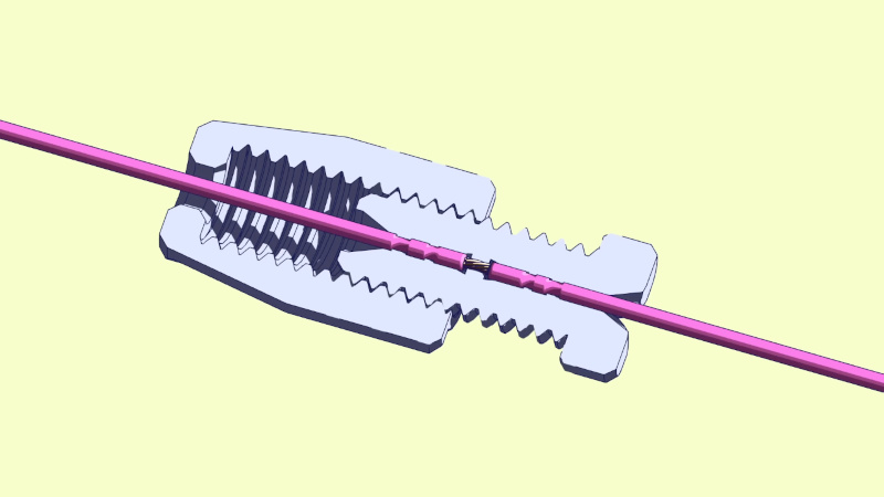
The operation is simple enough, a spring clamp encloses the join, and a threaded outer piece screws over it to clamp it all together. There’s a pair of 3D printable tools to aid assembly, and a range of different sizes to fit different wires. It looks well-thought-out and practical, so perhaps it could be a useful tool in your armoury. We can see in particular that for those moments when you don’t have the right connectors to hand, a quick 3D print could save the say.
A few years ago we evaluated a set of different ways to make crimp connections. It would be interesting to subject this connection to a similar test. Meanwhile you can see a comprehensive description in the video below the break.
Thanks [George Graves] for the tip.


The most relevant article that should have been linked to this one: https://hackaday.com/2020/06/11/retrotechtacular-wire-splicing-the-army-way/
in the video, it wasn’t the solder joint that broke, but the wire after the solder joint that broke, probably because of being flexed. I would be interested in looking at the wires up close after stripping to see if he nicked any of the strands.
But still, nice for temporary work. I use Wagos though.
Solder wicking up the wire and creating a flex point (which metal fatigues) is the reason soldered joins are frowned on in any space w vibration issues (cars, airplanes, you mom’s…)
Best reason to use crimped joins and to get a decent quality crimper.
You are so funny, can I touch you?
This is funny, cause you have the same name as the first comment.
I don’t think I have ever seen two wires soldered together coming apart at the solder joint itself, whether the wires were twisted together and soldered or just soldered side by side, as long as a significant amount of solder actually adhered to the wires. It’s always been a failure right beside the solder joint. That said, the 3D splice will help with such failures by keeping the wire rigid in the area where the wire is not protected against hard bends with insulation. Heat shrink can do a similar thing.
Solder causing a ‘hinge’ where any movement concentrates the metal fatigue into one spot is the reason why there are numerous automotive and aeronortical wiring standards that require crimped rather than soldered joints. It’s also why the folk wisdom of ‘belt and braces – add solder to crimped joints’ is so harmful
How does crimping not create a hinge area? I’ve, wrongly apparently, always assumed the dislike of solder in cars and such was because of solder cracking or something along those lines. Surely it must be a heat related thing.
Pardon me if I’m not seeing it clearly, I’m truly trying to understand the crimping not causing hinging.
Crimps of all types will have a radius that the wire will bend around at extreme.
Solder wicks up the wire inside the insulation and makes it solid for a small distance.
There is no radius, just a bend ‘point’ about as big as the wire diameter.
It’s the first place the wire can bend.
This has been studied to death.
NASA level.
The main knock on soldered connections in most wiring standards is that if the connection is just soldered and it gets heated enough, from its own current or another source, it can separate. The second knock is that it takes more time and skill to make a good solder joint than to crimp (assuming good crimp connectors and a properly set-up controlled-cycle crimping tool).
I don’t think this new screw-together idea is an improvement on what we currently have. It looks pretty unforgiving on the wire diameter, and is slower to complete than crimping.
This solder vs crimp holy war always comes up – while it’s true crimp is favoured for speed & ease of inspection as well as tolerating vibration more easily, a solder joint that’s then heat-shrunk to protect it can also be perfectly robust.
There’s NASA standards as well as numerous other very critical applications where crimp or solder are allowed as long as proper processes are followed for each. It’s the proper process that is the real key.
Crimp has the edge in industry because it is more idiot-proof to give people a calibrated crimp tool and proper crimps than a soldering iron, and you don’t have the associated risks around heat, fire risk, solder smoke, lead, etc.
On why anti-wicking tools are used in NASA/milspec soldering from Grok’s reading of NASA materials:
One of the primary reasons for this is to avoid vibration-induced fatigue failures. When solder wicks excessively up the wire (typically more than 1/8 inch under insulation), it impregnates the strands, creating a rigid, brittle section that concentrates stress at the transition point between the soldered and unsoldered areas. This stiffness makes the wire susceptible to cracking or breaking under repeated bending, flexing, or high-vibration environments common in aerospace and military applications (e.g., spacecraft launches or aircraft operations). Preventing wicking maintains the wire’s flexibility, distributes stress more evenly, and enhances overall reliability by reducing the risk of fatigue-related failures at the solder joint.
huh i always thought the great thing about twisting wires together is that it makes a joint that is stable enough that it’s easy to solder, without setting up your helping hand or whatever
Well done!
There is a nice document on joining wires from NASA: “WORKMANSHIP STANDARD FOR CRIMPING, INTERCONNECTING CABLES, HARNESSES, AND WIRING”
You can find it here: https://s3vi.ndc.nasa.gov/ssri-kb/static/resources/nasa-std-8739.4a.pdf
It is a good read. Highly recommend it.
Interesting and useful! But it reads like the ten commandments, it has 101 page and the word “shall” is mentioned 464 times :)
“Shall” is a specific phrase used to identify a requirement.
“Should” is a loose requirement that can be followed optionally.
You Shall reply to my comment (this is a requirement).
You should imagine Morgan Freeman narrating this standard. (not a requirement but a strong suggestion)
This means there are 464 Requirements in that document. there could potentially be some that are derived from that as well.
Welcome to the world of normative language. :D
https://datatracker.ietf.org/doc/html/rfc2119
Variation on an existing product. https://www.posi-products.com/index.html
And I would suggest buying these in any application that matters. 3d print for the prototype, use the real deal for the real world.
I really like this idea! 😃👍
Though there’s one thing that came to my mind instantly while reading: The over use of plastic in our lives.
I remember older electro installation parts being made of Bakelite and ceramic (such as luster terminals).
Same goes for older power cords that had a fabric insoluation (textile cable, silk-spun).
Elegant lamps for the living room of early 20th century used to use them, for example. Or irons.
Now, Bakelite is an early plastic, too and not very environmentally friendly, either. Some had asbestos mixed in.
But it was built to last, at least. We still have outlets and plugs made from Bakelite at home.
And it feels more like stone than cheap plastic.
This is chasing the rabbit. Electrical wiring should never be under tension. What counts in an electrical joint is low resistance and that is a function of pressure over area. This device minimizes connected area and seems somewhat critical of joint makeup. Being 3D printed means it that as the join heats under load, the connection loosens ending in a cascade failure.
Any power grid wire hung between towers or poles is under tension, although in some cases a steel core may take most of the mechanical load. The same applies to long wire antennas.
I second this! It’s funny how even a simple wire antenna made of an lightweight, 2,5mm ⌀ audio cable can become very heavy eventually.
No matter how much you try, it refuses to become a straight line. It always tries to bow down. 😂
And dont forget vibration, the wires in a harness in a car are not under tension, but they certainly get bounced around quite a lot, esp. off-road
I’m not sure you’re right here. For most metal, current goes through the surface of the wire, not the inner core (skin effect). Thus, the more contact from the surface of one side to the other side, the better. Think of it this way, when you crimp your wire, the only surface in contact of the wire is the (very small) area of metal you’re bending with your pliers. If you twist the wire strand, the surface is the number of strands multiplied by their diameter and pi. It’s obviously much larger than the outer surface of a circle.
In addition, when the wire are twisted, the friction force is much higher between each strand combined than from the inner and outer surface of 2 cylinders.
It’s no mystery that ropes are made by twisting/interleaving inner strands instead of knotting the 2 side.
So the video showing that twisting wire is stronger than the wire itself isn’t a discovery by itself.
In addition, the fast that the “nut” is long enough to distribute the bending force away from the connection explains why it’s stronger than a soldered joint. He would have had the same effect if he used heat shrink over its twisted wire, but without the fancy 3D printed nut.
If you think that a twisted wire will heat more than a crimped wire, you’re are greatly mistaken, again because the surface contact is much higher in the former case. If your wire heats so much at that connection (which will likely increase the local resistance by few percent only), then you’ve a lot of other problems to solve beforehand, like changing the wire diameter to support the current you’re using.
The main issue of this “crimping” mechanism is the nut itself: its size and weight. It doesn’t provide any waterproofing, it’s exposed to air (so it’ll oxidize). Mechanically, I doubt it’ll fail anytime soon, since you never put a wire under mechanical tension anyway. It should be safe for vibration, depending on the plastic used (don’t use nylon here).
skin effect applies only to AC
“A quick 3d print could save the say” (maybe a typo?)
OK, where can I but 50 each of #14, #12, #10 stranded copper? (i.e. boat or RV wiring)
Hey, maybe a bunch of smaller sizes also!
If you can’t crimp then use a Lineman’s splice covered with heatsrink tubing. A Lineman’s splice will provide excellent physical strength and electrical contact while the heatsrink tubing will provide insulation, mechanical integrity to the free ends of the wire and environmental isolation particularly if glue lined heatshrik tubing is used.
anyone else hum the a-team theme when they twist two wires together?
don’t you love it when a connection comes together?
Would someone download this from makerworld and upload it somewhere else like printables or thingiverse (non-commercially as per the license)? Makerworld seems not interested in allowing new accounts to be created.
People who make electrical connections by twisting wires together should be taken out and shot. It’s the preferred ‘install method’ for vehicle accessories I’ve seen around here, and I’ve also seen it gone bad countless times.
Oh the other hand, soldering+thermal shrink lasts forever (more than the lifetime of the vehicle), despite what NASA and their studies say. Never seen a single one fail.
Connectors can work too when crimped correctly and with a quality tool, but need space that’s not always available in tight spots.
A proper twisted splice is as good a connection as you can get. Even when soldering wires together they should be spliced first – the solder should never be the primary mechanical connection.
A dodgy splice job is a dodgy splice job, not evidence that splicing is inferior.
i think your ‘should’ there shows how there are big differences in attitude depending on what you’re doing.
i never do something safety-critical, or something that is more than a hack or prototype, so i don’t honor any “should”s. no one is paying me for my electronics work! i throw it together however it strikes my fancy, and i repair or discard depending on how frustrated i am.
about 15 years ago i had a kind of break through in my soldering…i used to preferentially twist my wires together before soldering, because it was such a convenient way to get them to stay together while i spent forever trying to heat them up enough to get solder to flow onto them. but then i realized, if you tin the wires first (i was taught this as a child, but had to rediscover it when i was grown), then you can merely lay them side-by-side parallel to eachother and then touch the iron to them and — if you tinned them “heavy” — the solder flows between them and makes a “strong” bond. which is what i think you are calling “a dodgy splice job”. and, because i’m neat these days, then i heat shrink it if it’s convenient.
the thing is, i’ve never had one fail. it’s never been the cause of the frustration that makes me throw out the prototype :)
There are tons of underground splices in communication line that are twisted and most central offices are packed with wire wrapped connections so the idea of twisting wire not working is ridiculous.
Cool… a new way to make dodgy bulky wiring that makes your build looks awkward.
Although I do like the effort put into it, the conclusion “stronger than a solder joint” is simply not true although if you don’t know how to make a decent solder joint than it might be true though.
The real problem is not the connection itself, but strain relieve and bend radius.
It does make me wonder how the connection on the business end of the wire will be made… soldering… a crimp connector…
^ this is essential reading.
I’ll throw this one into the mix too:
https://www.rbracing-rsr.com/wiring_ecu.html
On fabricating professional motorsport wiring harnesses
Argh that was supposed to be in response to halogenek’s link to NASA workmanship standards.
I guess HaD comments are broken again.
This works great when you have access to the end of the wire. But if there’s a big connector on both ends or it goes up into a wall or something, then it doesn’t work. Perhaps an improvement would be that the wire could slot into the joiner, or have two halves that can come together. It is necessary for 360 degrees around the wire to be held?
I guess if the wire is already broken, then you do have access. Where’s my edit button?
I don’t get it. This doesn’t make sense to me because, for all that faffing about, the two wires are still in a straight line butted up against each other.
A real system for alleviating strain on a join would have both wires looped or bent around something solid that takes ALL the strain off the join completely. Like plugging together two extension cords with the ends knotted around each other, so that no amount of pulling on either end can ever separate the plugs.
Seems like it’s work well but what about oxidation of the twisted join over time?
I tend to not have wires prone to strain in the first place though.