Last time, we built a case for a PCB that handles 100 W of USB-C power, an old project that I’ve long been aiming to revive. It went well, and I’d like to believe you that the article will give you a much-needed easy-to-grasp FreeCAD introduction, Matrix knowledge upload style, having you designing stuff in no time.
Apart from my firm belief in the power of open-source software, I also do believe in social responsibilities, and I think I have a responsibility to teach you some decent FreeCAD design practices I’ve learned along the way. Some of them are going to protect your behind from mistakes, and some of them will do that while also making your project way easier to work with, for you and others.
You might not think the last part about “others” matters, but for a start, it matters in the ideal world that we’re collectively striving towards, and also, let’s be real, things like documentation are half intended for external contributors, half for you a year later. So, here’s the first FreeCAD tip that will unquestionably protect you while helping whoever else might work with the model later.
Okay, we’re all hackers, so I’ll start with zero-th FreeCAD tip – press Ctrl+S often. That’ll help a ton. Thankfully, FreeCAD’s autorecovery system has made big leaps, and it’s pretty great in case FreeCAD does crash, but the less you have to recover, the better. Now, onto the first tip.
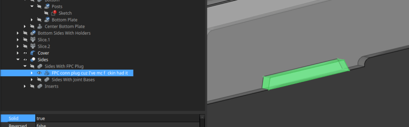
Name Your Bodies, Always
The button is F2. That’s it. Click on your models in the tree view and give them a name. Do it for all extrudes, cuts, and even fillets/chamfers. You don’t have to do it for sketches, since those are always contained within an extrusion. If at all possible, do it immediately, make it a habit.
Why? Because names make it clear what the extrusion/cut/fillet is for, and you’ll be thankful for it multiple times over when modifying your model or even just looking at it the next morning. Also, it makes it way easier to avoid accidentally sending the wrong 3D model to your printer.

How to make naming easier? I’ve figured out an easy and apt naming scheme, that you’ve seen in action in the previous article. For Fusions, I do “primary object +addition” or “with addition”, mentioning just the last addition. So, “Bottom case +cutouts” is a cut that contains “Bottom case +logo” and “Cutouts”, “Bottom case +logo” is a cut that contains “Bottom case” and “Logo”, and “Bottom case” contains “Bottom floor” and “Bottom walls”.
It’s not a perfect scheme, but it avoids verbosity and you have to barely think of the names. Don’t shy away from using words like “pip” and “doohickey” if the word just doesn’t come to your mind at the moment – you’re choosing between a project that’s vaguely endearing and one that’s incomprehensible, so the choice is obvious. Naming your models lets you avoid them becoming arcane magic, which might sound fun at a glance until you realize there’s already an object of arcane magic in your house, it’s called a “3D printer”, and you’ve had enough arcane magic in your life.
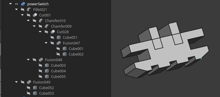
Last but not least, to hack something is know learn its true name, and whatever your feature is, there’s no truth in “Cut034”. By the way, about FreeCAD and many CAD packages before it, they’ve been having a problem with true names, actually, it’s a whole thing called Topological Naming Problem.
Naming Is Hard, Topology Is Harder
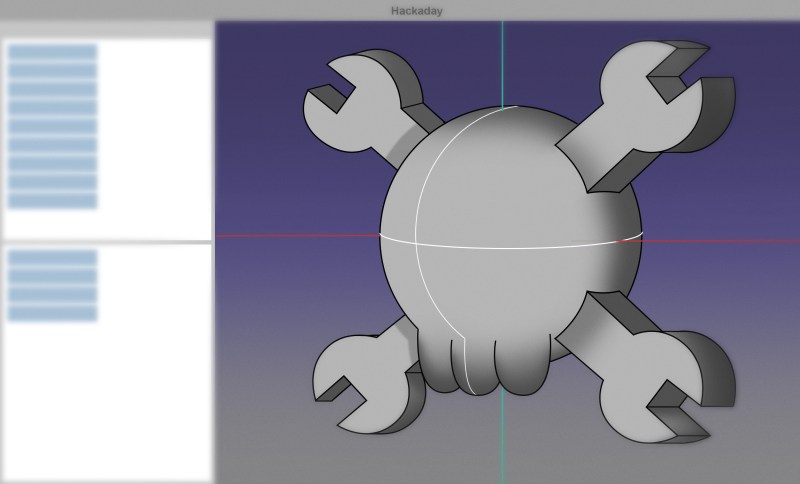
How do you know where a feature really is? For instance, you take a cube, and you cut two slots into the same side. How does the CAD package ensure that the slots are on the same side? One of the most popular options for it is topological naming. So, a cube gets its faces named Face1 through Face6, and as you slowly turn that cube into, say, a Minecraft-style hand showing a middle finger, each sketch remembers the name of the side you wanted it attached to.
Now, imagine the middle finger hand requires a hole inside of it, and it has to be done at from very start, which means you might need to go back to the base cube and add that hole. All of a sudden, there will be four new faces to the internal cube that holds the finger sketches, and these new faces will need names, too. Best case, they’ll be named Face7 through Face10 – but that’s a best case and the CAD engine needs to ensure to always implement it properly, whereas real world models aren’t as welcoming. Worst case, the faces will be renumbered anew, the sketch-to-face mapping will change which faces get which names, and the model of the hand will turn into a spider. Spooky!
It’s not Halloween just yet, and most regretfully, people don’t tend to appreciate spiders in unexpected places. Even more sadly, this retrospective renaming typically just results in your sketches breaking in a “red exclamation mark” way, since it’s not just sketch-to-face mappings that get names, it’s also all the little bits of external geometry that you’ll definitely invoke if you want to avoid suffering. Every line in your sketch has an invisible name and a number, and external geometry lines will store – otherwise, they couldn’t get updated when you change the base model under their feet, as one inevitably does.
This used to be a big problem with FreeCAD, and it still kind of is, but it’s by no means exclusive to FreeCAD. Hell, I remember dealing with something similar back when my CAD (computer-aided despair) suite of choice was SolidWorks. It’s not an easy problem to solve, because of the innumerable ways you can create and then modify a 3D object; every time you think you’ll have figured out a solution to the horrors, your users will come up with new and more intricate horrors beyond your comprehension.
FreeCAD v1.0 has clamped down on a large amount of topological naming errors. They still exist; one simple way I can trigger it is to make a cutout in a cube, make a sketch that external-geometry-exports the cut-in-half outwards-facing line of the cube, and then go back and delete the cutout. It makes sense that it happens, but oh do I wish it didn’t, and it makes for unfun sketch fixing sessions.
How To Stay Well Away
Now, I’m no stranger to problems caused by name changes, and I’m eager to share some of what I’ve learned dealing with FreeCAD’s names in particular.
The first solution concerns cutouts, as they specifically might become the bane of your model. If you have a ton of features planned, just delay doing the cutouts up until you’ve done all the basics of the case that you might ever want to rely on. Cutouts might and often will change, and if your board changes connector or button positions, you want to be able to remake them without ever touching the rest of the sketch. So, build up most of your model, and closer to the end, do the case cutouts, so that external geometry can rely on walls and sides that will never change.
Next, minimize the number of models you’re dealing with, so that you have less places where external geometry has to be involved. If you need to make a block with a hole all the way through, do it in one sketch instead of doing two extrudes and a cut. You’ll thank yourself, both because you’ll have less opportunity for topo naming errors, but also because you have fewer model names to think up.
The third thing is what I call the cockroach rule. If you see a cockroach in your house, you back off slowly, set the house on fire, and then you get yourself a different house, making sure you don’t bring the cockroach into the new house while at it. Same can apply here – if you remove a feature in the base model and you see the entire tree view light up with red exclamation marks, click “Close” on the document, press “Discard changes”, open the document again, and do whatever you wanted to do but in a different way.
Why reload? Because Ctrl+Z does not always help with such problems, as much as it’s supposed to. This does require that you follow the 0th rule – press Ctrl+S often, and it also requires that you don’t press Ctrl+S right after making those changes, so, change-verify-enter. Thankfully, FreeCAD will unroll objects in the model tree when one of the inner object starts to, so just look over the model tree after doing changes deep inside the model, and you’ll be fine. This is also where keeping your models in a Git repo is super helpful – that way, you can always have known-good model states to go back to.
Good Habits Create Good Models
So, to recap. Save often, give your models names, understand topo naming, create cutouts last if at all possible, keep your models simple, and when all fails, nuke it from orbit and let your good habits cushion the fall. Simple enough.
I’ll be on the lookout for further tips for you all, as I’ve got a fair few complex models going on, and the more I work with them, the more I learn. Until then, I hope you can greatly benefit from these tips, and may your models behave well through your diligent treatment.


In short, prefer using PartDesign to Part workbench. If you think in boolean operation too much (Cut / Union / Intersect), you’ll end up with unsolvable and unmodifiable mess. Make the most you can in PartDesign (with sketches) and only reserve the most complex task to Part workbench.
I’m with you on this one! Because the CSG workflow is comfy for me (OpenSCAD), I tried to use Part like this a lot when I was starting out in FreeCAD.
But in the name of simplicity of defining the specs, and making things easily alterable later, I learned the Part Design / Sketch workflow. It seems like FreeCAD really wants you to go that way.
I will have to agree. Even if its a quirk of FreeCAD, I think its still worthwhile building a mental model and workflow where everything is based on modifying the original sketch. This lets you think about the model in a systematic way, which is an important part of planning anyway
The “adding/subtracting primitives until it looks like you want” is quite akin to how CAD was done in the past. It makes sense for OpenSCAD but for FreeCAD you don’t want to do that…
Any good tutorials on FreeCAD? I’m using Onshape but FreeCAD is free and performs way better than a web-based software like the latter.
My tip for FreeCAD is to try to avoid attaching sketches to faces in PartDesign. Attach them to the axis planes or datum planes instead and add offsets if necessary. Makes it less likely to mess up the whole model if you change things later…
+1, it really changes everything, ans with the help of spreadsheets you can have incredible parametric models that don’t break easely. With little python scripts you can also re export all the parts in one button clic :)
Check MangoJellySolutions. He has released numerous youtube video tutorials for FreeCAD. He does an excellent job. Just be careful to verify that the tutorial is for the proper version of FreeCAD as there have been considerable changes made.
haha yeah i try to make projects readable for other people because the other people are always me a year later. i’ve got build diaries up into the tens of thousands of words so i can look back and figure out what that stranger who sits in my chair was thinking a decade ago.
i don’t use freecad, and the ctrl-z discourse in this article makes me really glad for it! i want robust change management for everything i do on the computer. i am always checking things into git, and i need the diffs to be intelligible. that’s why i could only use a script-based cad, and for me that’s openscad. i do break the whole model for a simple change, but i always can see exactly how that happened and i never have to superstitiously kill the program just in case its own change management has side effects and can’t unroll the past with veracity.
Learning FreeCAD now. Fully agree with the need to name things. You will be thankful when, not if, a tiny change breaks any or all fillets/chamfers.
If I’ve only learned one thing about FreeCAD, it’s that you do chamfers and fillets last. (Oh, and look carefully after using them because they have a habit of making parts of your model disappear.)
If you’re learning, don’t forget about Spreadsheet workbench (that’s where the magic of parametric design goes). In fact, FreeCAD should refuse to type a number that’s not from a spreadsheet cell, because if you do so, chance are high you’ll make a mistake and modify this number (or forget about it) later on and this will break the constraints.
In all CAD software I’ve used, you need to follow the robust modeling rules (described everywhere, search for google, like https://www.engineersrule.com/building-an-unbreakable-model-by-laying-the-foundation/ ). In short, you’ll start your design with the most important features first (no details, only primary features, all the mechanical architectural stuff first), and then add the secondary features (cuts/pocket/…) and finish by the details (like fillet/chamfer). That way, if anything breaks due to a parameter change, only the latter steps needs to be redone.
Said differently, the part number of face must only increase in construction order, and not the opposite. Most problem arise from removing faces, not adding them.
I’ve seen, but haven’t played with the spreadsheet feature yet. It does seem enticing and highly useful. The concept of “parametric” modeling was a little bit lost on me. Then I saw that. It’s on my to do list.
In my experience/ignorance, FreeCAD has broken things in very unexpected ways. For example: I have a 10mm thick, about 40×50 base (below some other stuff) with a bottom-up counterbore through the base. When I chamfered the outer edge of the bottom of the base, the counterbore broke (and I completed a 4-5 hour print before I noticed it). I still don’t get that one. It seems that something went unhappy related to the face with the pockets that was later chamfered. V1.x is still early days. I’m not yet asking for a full refund of my purchase price.
Chamfers/fillets and “wire not closed” are my biggest headaches so far. Oh, and wrapping my head around “fully constrained” without hitting “over constrained”. Oh, and putting text on/in my models. Oh, and keeping track of which workbench I need for what…
You can teach an old brain new tools, if a bit slowly.
I’ve simultaneously been learning Fusion 360. I have to say it’s easier for me to use at my elementary level, but I’m not able/willing to pay the price of admission once I (if I) manage to creep past that “non-commercial use” threshold. I don’t expect to ever leapfrog past it to where the cost is comfortably absorbed by my meager commercial dabblings. So, I’m living and learning FreeCAD. I also prefer to have full access to, and control over my drawings.
It’s irrelevant to the topic at hand, but for some reason my brain has, today, taken to typing “Fred” while it’s supposed to be typing “FreeCAD”.
Thank you to any FreeCAD contributors who might be reading this.
If you change a chamfer in a complicated part it can change the part’s edge numbers and break chamfers higher up on the hierarchy.
They’re usually still there, but on the wrong edge.
Sometimes, they make the whole part disappear.
Yeah that constraint one is always interesting, especially on the complex sketches you add a feature too. Fortunately for most projects if you can’t figure out how to get a comfortably constrained sketch you can still work with it ‘broken’, so knowing when it is worth fixing that problem rather than just taking a fresh save as backup and working forward. The others are more just learning the logic and structure of FreeCAD, you’ll get there if you keep using it.
Indeed, can’t echo that thought strongly enough. Including the many folks that are not directly FreeCAD contributors but helped me get over that initial learning curve with the now horrible outdated version of their guides to something back when I first started trying to use it..
Quick thought – fully constrained is nice, but it’s mostly for your own benefit (making sure the sketch adapts to future changes to the underlying faces and reference geometry) than anything else.
@Arya indeed, but its all about knowing when it is worth the effort to chase down a properly constrained sketch.
For instance I have a sketch on a project that is overconstrained, but that sketch really isn’t worth restarting the constraint setup again after the change that lead to overconstraint – its a finished part now, any future changes to anything else in the project can’t break it, and should I ever need to really adjust that part with how skeletal it must be to function the new version wouldn’t bear any great resemblance to the current one – its a complex fan bracket so minimal material in the blade path while being able to accommodate I think its 3 sizes of PC fan – but if I wanted to say pivot to a 2×3 grid of the smaller fans or have the single huge fan overhang the rest of the part to get enough cooling as the 1×2 or 1×3 grid of currently supported sizes are insufficient everything would have to change.
But in that same project I also have an underconstrained sketch, and that one is one of the most likely to change – all the most crucial tolerances that are parametrically adjustable interact with that sketch, and one of the changes I needed to make broke it. So that one is essential to work on before doing anything else – I think with how fiddly the sketch is I will end up breaking it into 3 or 4 sketches, which will mean I could end up with some fillets I’ll have to add in manually afterwards, or just accept less than smooth transition between the important mating surfaces in the CAD knowing 10 seconds with a file in the real world will fix the problems…
For the “wire ils not closes” issues, i use the sketcher_validate-sketch tool, it shows problematic intersection of a sketch. Magic!
As somebody who works a lot with other people’s CAD, coming from professionals and plenty of nice and expensive stock models, I can say that the number of models where any parts are labeled is very easily within the margin of error of 0%.
yeahhhhh it used to be the same with open-sourcing 3D models, too. I think we can change that and we ought to change that, and the first step is talking about it, I suppose.
The best practice for FreeCAD user is to uninstall it and get something that is actually user-friendly…
Oh, you.
Are you buying?
LOL!
My thoughts exactly.
Every now and again, I think about giving FreeCAD a try and then I’ll read something like this.
Yikes
There aren’t any.
It’s just a complicated problem, solved with tedium, industry wide.
Closest I’ve found to ‘user-friendly CAD’ is ‘artsy-fartsy VR sculpting’ like ‘Shapelab’. Where everything is about extruding or removing virtual clay and undo. You can’t do a part in it, but boobies! Right tool for the job.
First CAD program I used was AutoCAD for DOS.
Worst ‘CAD program’ I’ve ever used is Blender.
I can kind of agree with this. Though, I went through 3 different pieces of CAD software on my computer before settling down on my current choice at the end.
Sketchup to start out before I even knew what CAD meant and it was still owned by Google at the time and ran locally, Autodesk Inventor 2017 since I had a free license for it in high school but has since been expired but was still fantastic to use at the time, Fusion360 which felt limited and made me increase my hate for cloud based software and SaaS that Adobe had ignited in me beforehand, FreeCAD well before the 1.0 version and before they even had the ability to do chamfers (which made me drop it once I realized it wasn’t ready for showtime yet), and Alibre Atom3D.
Alibre Atom3D was what I am currently on and has felt so familiar to a fusion of Fusion and Inventor with more features than the first and less features than the second, respectively. Even though I’m financially fine with the upfront cost of each new license that I realized I had to get when my old computer had done it’s last power down when I was away, and the yearly fee of $50 to get updates, I’d like to see FreeCAD reach that level so I can switch my yearly subscription to a yearly donation to help them out instead for helping me out of a majority-on-top SaaS world and some other terrible business practices for hobbyists and at-home users who aren’t really using it to make money or be a business but just to make things to make life easier. I’ll give it another spin soon and hopefully see it reach a primetime level for hobbyists in the near future.
In freecad you MUST care about topology by yourself. I mean instead:
1. make cube
2. attach sketch on cube side and draw circle
3. make circle hole
4. attach sketch on cube side with hole and draw octagon
5. make octagon hole
6. remove circle hole and break octagon sketch
you need
1. make cube
2. attach sketch on cube side (maybe instead plane enough for you?) and draw circle
3. make circle hole
3.1 switch to cube in tree again
4. attach sketch on cube side without hole exists and draw octagon
5. make octagon hole
6. remove circle hole and octagon hole still exists
Thanks. Definitely keep the tips coming!
I really prefer the mildly buggy free software to still buggy paid services, but it can be a hassle to change tools.
Another tip: Other than saving using ctl + s, do some versioning every hour or so or at least before a big and dangerous change. Once you get to Version_999, you can start deleting the older ones … or use Github.