If you want to protect a system from being hacked, a great way to do that is with an airgap. This term specifically refers to keeping a system off any sort of network or external connection — there is literally air in between it and other systems. Of course, this can be limiting if you want to monitor or export logs from such systems. [Nelop Systems] decided to whip up a simple workaround for this issue, creating a bespoke one-way data extraction method.
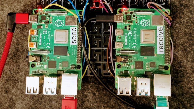
The concept is demonstrated with a pair of Raspberry Pi computers. One is hooked up to critical industrial control systems, and is airgapped to protect it against outside intruders. It’s fitted with an optocoupler, with a UART hooked up to the LED side of the device. The other side of the optocoupler is hooked up to another Raspberry Pi, which is itself on a network and handles monitoring and logging duties.
This method creates a reliable one-way transmission method from the airgapped machine to the outside world, without allowing data to flow in the other direction. Indeed, there is no direct electrical connection at all, since the data is passing through the optocoupler, which provides isolation between the two computers. Security aficionados will argue that the machine is no longer really airgapped because there is some connection between it and the outside world. Regardless, it would be hard to gain any sort of access through the one-way optocoupler connection. If you can conceive of a way that would work, drop it down in the comments.
Optocouplers are very useful things; we’ve seen them used and abused for all sorts of different applications. If you’ve found some nifty use for these simple parts, be sure to drop us a line!


You could use a fibre optic network and just connect one side. Much more data. Possibility to directly send it off to a logging server, cloud, whatever. No need for a second RasPi.
That’s basically what the ‘data diode’ product category is; just done particularly carefully and documented so that it can be sold as EAL 7/7+.
Aside from the compliance paperwork; there’s also some value-add in terms of various software add-ons that try to keep software that expects a bidirectional connection from freaking out in the presence of a unidirectional one so that you can use at least some software un or minimally modified.
If you aren’t doing military procurement; you can, presumably, get most of the effect by just hooking up only half of the fiber pair.
Obviously you can’t fake replies that are genuinely unknown or meaningful; but (especially if the data diode is on a well behaved bit of network, not congested or dropping packets or the like) you can do a lot by just having a shim on the sending device that fakes acknowledgements that the receiving device is incapable of sending.
If you are doing custom software or adopting something designed for streaming or broadcast or similar cases where acknowledgements are not assumed and occasional losses are handled by just adding a bit of redundancy up front you can get away with doing less lying; but some clever lies on the sender side will allow normally bidirectional protocols to at least try to work rather than just fall over and die immediately.
Old 10-base-T Ethernet cards had a 15-pin D connector to attach a “media access unit” (MAU). You could get them for thicknet (RG8 CoAx), thinnet (RG58 CoAx), 10BaseT (RG45) or fiber optic.
We needed to be able to send commands to a classified system from an unclassified system.
We used fiber optic MAUs, disconnected the TX fiber on the classified device and sent commands to it using UDP. Point to point there was no risk of collision, so UDP was reliable for our purpose.
Ah, the fiber optic data diode. UDP is your friend.
For more modern systems with RJ-45 connections, we’d use fiber optic ethernet media converters. Weird setup since the media converters needed to see light on RX to believe they had an active line so you had to hook up a 3rd converter to provide it.
You don’t need a full-blown MAU to do this. Just the TX pair from the usual RJ45 works fine, even at 100 Mbps.
We needed to send 100 Mbps from a rotating platform. Slip rings wouldn’t do the speed. Optical couldn’t do the rotation. COTS RF solutions at the time were too slow or too expensive. A simple capacitive-coupled balanced “antenna” (non-contact coupler) worked, with a bit of signal conditioning. We did have a 115200 bps backchannel over a slipring to control the comms and send checksums/retries, but the bulk transfer was, like yours, plain old byte UDP packets. The checksums weren’t needed: Our bit error rate was zero (unmeasurable).
That was turn of the century. They’re at 40 Gb/s now, and the couplers are far more sophisticated. I don’t know what magic was conjured to make that possible, because it isn’t, on paper.
Then you don’t have an air gap. We only connected fiber, not copper.
Well, it’s capacitively coupled, so technically it is air-gapped. Just a very small gap.
Hate to press more but what do you mean by antenna? I’m familiar with capacitors but do you mean you had a millimeter or so gap between the two “plates”? If so what kind of voltages were you driving this thing at?
That’s exactly right: a transmission line differential pair wrapped around the circumference of the rotating part (a few meters), driven by just a few volts (5V drive into what I’m just guessing is a 1:1 balun). The stationary “antenna” was 20 cm short section of similar transmission line pair, 1-2 mm over the rotating part flying underneath it at around 10 m/s.
That’s clever. I haven’t worked with fiber optics outside of research contexts. Ie modifying fiber to do thinks it’s uh not sold for. How do people go about disabling fiber in industry?
I’m all in favor of HaD taking up the mantle of 2600 magazine, so this isn’t a complaint, but obviously this does defeat the (questionable) concept of an air gap, which is to make access physically impossible.
There could be information leaked in the log data or a side channel that was supposed to be secret, or perhaps could be used to acces the Raspberry Pi through the wifi interface that it has, and from there access the target system, etc. It’s unlikely, but you can’t rule it out, and then why not just make life easier by networking the thing and hoping your firewall is up to the job?
It still goes through an air gap, you see.
Even more pedantic perhaps, but most optocouplers I’ve cracked open are actually an epoxy moulding around a solid lump of some sort of optical plastic so there’s no air inside them.
Wifi goes through an airgap too ;)
If this optocoupler setup breaks the air gap, then so does attaching a monitor to the machine does so as well. Heck, by your logic, if a computer has any way to affect the outside world (i.e do anything), then it isn’t air gapped.
Yeah, that’s why I say the whole concept of an air gap is questionable. A system is either provably secure or it interacts with the rest of the world in any way whatsoever.
If you connect a monitor to a computer, you’re basically turning it into a public-access TV channel as far as van Eck phreakers are concerned
This is a one-way-transfer, not an “air gap” as it would literally need to be completely disconnected. One way transfers work great and are used in some industrial networks for sending system telemetry data out, for instance, to an ops center for monitoring. Van Eck is a thing, of concern in SCIF’s and not so much for other environments.
Yes, log data can leak sensitive info out, but if your threat model is an attacker gaining remote control over a device, this is just as secure as not having anything between them at all. Even if you got root access on the networked Pi, you can’t do anything on that pin to influence the secure Pi
…unless you can?
I mean, you could just network the target machine, and say “you can’t do anything on the single exposed HTTPS port to influence the rest of the system”. Much of the time this is true!
There is significant C across the optocoupler. Using a high voltage, fast rise time, common mode signal applied to the phototransistor (i.e. to both pins) , you can send a signal to the LED pin.
Assuming root access, and the LED connected to a pin with an input mode of some sort, then you can send commands backwards through the opto.
Replace the optocoupler with a TOSLINK cable then. The transmitters and receivers are readily available and will work fine with UART data. That makes an optocoupler with a gap that can be up to 10 meters across.
The receiving system still needs to be correctly designed for this to be secure. Think Little Bobby Drop tables.
If you design an airgapped protocol, maybe not sending commands along the sensor data and not executing arbitrary data might help. It’s easy to tokenize, set max length, check if data is float or integer and then save it. I really find this bothersome to assume that the creator would even design such an implied footgun.
I wasn’t familiar with the term. So I looked it up. I rolled over laughing at the comic clip. Thanks for the chuckle!!!
Sure, but the point of this is to protect the sensitive system that’s sending logs, not the one receiving the logs.
If you really think this is not enough and need more airgap then have a display on the safe machine and a camera with OCR on the logger. You can even separate the two machines with bullet proof & water proof glass…..
Used an opto isolator? He took the term air gap to literally. Anyone who actually knows anything about electronics would know that using a UART aka RS232 IC TX pin is an output only pin. The opto did nothing to help the matter.
B-b-but muh ruspbery pie! It’s a PROJECT you dumb hater.
When you need the approval of the DoD representative to connect your insecure system to theirs, you do what you need to assure them that data cannot leak.
In this particular scenario, these are just RPi GPIO pins 8 and 10 which can work as TTL UART (which is 0V – +3.3V and is not ±15V RS232 compatible, by the way) but can also be reprogrammed to do something else, including data reception on the “TX” pin. The optocoupler makes it much easier to pass an audit, if nothing else.
The TX pin might accidentally become configured as an input and if your RX pin can also be configured as an output then data can flow in the other direction. Chances are low. But not 0.
Short circuiting or adding current to the TX pin might create side effects in the device. If the device is off you might even be able to power the device via the pin. Side channel affects may be possible.
If both units share the same power supply there might me a possible side channel attack via power supply (voltage ripple/spikes or RF). An optocoupler doesn’t need a common ground and makes isolating power supplies easier.
The voltage ripple of the device might reveal private information about the device. If the optocoupler has a schmitt trigger build-in it is purely digital and won’t reveal analog information about the target. Except the timing of the signals. Without it you could configure your RX pin as analog and capture private information.
An optocoupler prevents data flowing in the other direction and limits what data can flow regardless of the firmware.
It might be overkill, but it’s cheap.
You can still exfiltrate/leak sensitive data. During the LED ON phase any fluctuation on the power line due to e.g. cryptography in another task can be detected on the receiver side.
Eh, I’m not so sure. This has the same attack vector as someone putting a current/voltage sensor on the pin. Pretty unlikely. Even still, the sample rate is so high for a CPU I really doubt there’s any practical way anyone could do that in a meaningful way anyways especially if there are any capacitors inbetween. I’d love to read an article where someone has pulled this off and gotten anything out of it in a plausible scenario. I just doubt it.
Pretty sure that is completely besides the point here.
It’s not about data being exfiltrated/leaked – it’s about no one external gaining control about the system.
Correct. But if the optocoupler has a schmitt trigger build-in it is purely digital and won’t reveal analog information about the target. Except the timing of the signals.
Meh. Did this about 20 years ago with a 2313 and an opto, but mostly for monitoring a system that required galvanic iso.
In any case, is this some sort of company’s ad?
TV remote control. One-way. No way isthe TV going to affect the remote, not directly anyways.
Could you exfiltrate data through the optocouplers, on top of the serial protocol? Probably if the PIs talk directly to the hardware. Optocoupler probably supports higher frequencies than serial.
Should hook up dumb serial chip, that can not be exploited by the PI. Optocoupler driven by the PI is allowing the complex system, that one is worried about, a direct control, allowing attacker to add protocols on top of the serial.
This smells like MIDI.
Another idea would be spdif over toslink.
I have not tried this but I have the hardware for it.
I did this once with an audio SOC. UDP connection and SPDIF output were both abstracted as FILE pointer. I tried to transmit some test packets with triangle wave and wondered why I couldn’t receive anything. I have to say that listening ethernet headers isn’t a good idea. Payload sounded like a tringle wave.
Thats pretty secure. 1 way pin with optical coupling. Reminds me of how I – as a gag – made a microphone jack optocoupler with a photodiode and got data off of my ipad because I didn’t want to buy some proprietary thunderbolt hoojamawhat. I think the only attack vectors here are physical, or down to the raspberry pi exploits themselves. Maybe I lack creativity.
KISS… Why bother at all devising yet another interface when you can throw in a $5 cable and be done with it?
It is challenging to send commands/attacks backwards through an optocoupler. It is not challenging to send them back down a wire.
If the power level of the led can be impacted by the processing power of the system while performing work it can potentially be leaking unintentional information. Goes for any RF emissions as well.
In Sweden this is called RÖS, RÖjande Strålning (Revealing Radiation/Emission), which is the side effect of for example the fluctuations in power when doing some processing.
As far as my experience goes, only having remote access to the receiving Pi, it will be more than difficult to get anything useful out from the transmitter Pinot to mention getting something in.
Best way of affecting transmitter is maybe to override the data transmitted to the logging computers and make the supervisor personnel shut of the transmitting system because it looks like it “going bananas”.
I doubt you can configure the receiving pin in a way that you get the fidelity (of the power into the transmitting LED) needed to draw any conclusion of other things than the data over the optocoupler . If you have the possibility to measure the power-level of the optocoupler LED you have most likely direct physical access to the system itself, that’s not what this system is designed for.
I think this is a very good project to demonstrate a way of making it very difficult to manipulate the transmitting system (in a harmful way) from only gaining access to the receiving Pi.
I will guess that the system that produce the logs might not be a Pi, a PLC or other microcontroller outputting a serial-stream of log data. But for the project it’s handy to use one…
Correct. But if the optocoupler has a schmitt trigger build-in it is purely digital and won’t reveal analog information about the target. Except the timing of the signals.
Do these Raspi’s have the Wifi radios disabled? No? then airgapped doesn’t mean what you think it means. You might need access to the internal network to install an exploit, but it’s possible to do so to defeat the “air gap”
You really need to think about your threat model before designing something like this. If your threat is a ransomware gang, this might be sufficient. If your threat is a state actor, likely not.
To be fair if the threat is a state actor there isn’t much of anything that can be done. Especially if they are on site.
I can pretty much guarantee rpis have wifi and ble exploits. But I’d also imagine both networks would also have black listed devices on the other. So it would have to be one of those very coordinated unlikely scenarios
It has been a very long time since I had anything to do with the things, but I remember back in the 1990s this was method of monitoring seasonal maximum demand (half hourly) electricity meters. At the time more for electrical isolation than security. The protocol was dead easy. One flash of the led for a known W/h value. The monitor just counted them over each half hour.
Security aficionados will argue that the machine is no longer really airgapped because there is some connection between it and the outside world. Regardless, it would be hard to gain any sort of access through the one-way optocoupler connection. <— they are wrong, lol. These geniuses should check how it works, there is literary diode and small solar panel and… air gap between them.