If you’ve never heard of the threadless ball screw, which was invented over sixty years ago, [Angus] of Maker’s Muse has a video demonstrating the whole thing, covering its history and showcasing both its strengths and weaknesses. If you like seeing mechanical assemblies in action, give it a watch.
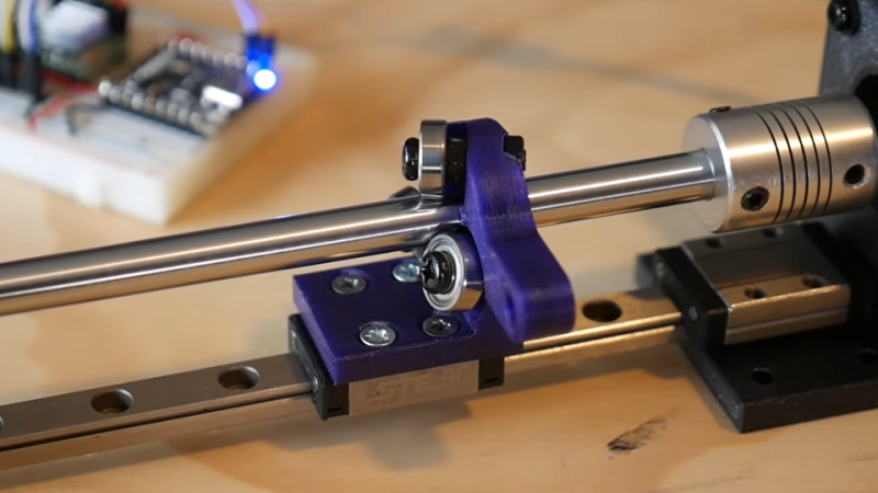
The device — consisting of little more than a smooth rod and three angled ball bearings — is a way to turn rotational motion into linear motion. Not a single belt, thread, or complex mechanical assembly in sight. While a simple nut on a threaded rod can turn rotation into linear motion, those come with their own issues. The threadless ball screw was one effort at finding a better way.
Threadless ball screws never really took off, although they were given some consideration for use in 3D printers back in the RepRap days. Today one can purchase quality CNC components without leaving one’s web browser, but back in the early 2000s things like lead screws and ball screws were rather more specialized, less accessible, and more expensive than they are today. RepRap folks had to make their own solutions. But while the threadless ball screw is a very DIY-friendly design, it was ultimately lacking in performance.
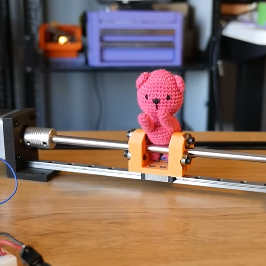
The main problem is they’re just not precise enough for anything like CNC work. [Angus] does some back-and-forth tests with a 3D printed unit that shows serious drift after only a few minutes. Now, he knows perfectly well that his 3D-printed test unit is far from ideal, but the rapidity at which it drifted was still a surprise. Making a carriage with two threadless ball screws — one at each end — performed a lot better, but was ultimately still flawed.
It’s not all bad. There’s zero backlash. They are mechanically simple, remarkably smooth, and utterly quiet. Also, [Angus] discovered that the maximum force this setup can be made to apply is surprisingly significant, and is directly related to the tension on the bearings. That means one can trivially adjust how easily the carriage slips (or doesn’t) just by tightening or loosening the screw holding each bearing.
Sure, they’re not precise. But maybe you don’t need precision. Maybe you just need to move something back and forth in a strong & silent sort of way that can still slip gracefully (and quietly) if something goes awry, like bottoming out an axis. 3D printing makes it pretty easy to whip one up, so maybe there’s still a place for the threadless ball screw.


Couldn’t you make a mix? I.e. a threaded rod, and then 3 bearing at 45 degrees, with a sharpened ring fastened on the outer runner of each bearing, which slots into the thread of the rod? Wouldn’t that have the precision of the threaded rod, but with very low friction, and no backlash?
Three flanged ball bearings on a trapezoidal thread?
I’m not sure it would be better than the threaded rod and its nut in terms of backlash, but it could be an alternative if you wanna avoid lubrication.
The poor man’s ballscrew.
Roy Featherstone’s version is absolutely fascinating and really shows the power of understanding geometry: http://royfeatherstone.org/ringscrew/index.html
Also, Joe Belter had a version of the linear bearing screw at the Yale GRABLab which did dynamic power balancing using a sprung mechanism, which is also really cool: https://www.eng.yale.edu/grablab/pubs/Belter_TRO2015.pdf
I know of this system because it’s a problem in trying to support a long shaft with a bearing in the middle.
If the bearing isn’t snugly fit with the shaft, such that the shaft has some play inside the bearing – which is often necessary to get the bearing in the middle of a long shaft in the first place – then any misalignment of the two will make the bearing “swim” up and down the shaft. It’ll try to climb up the shaft and then pop back.
There’s almost no need for positional accuracy on the screw if you’re using a linear encoder on the table. You keep running until you hit your target. Anywhere that it’s even remotely viable to use closed loop positional control, you should.
The hard part is coming up with the linear encoder.
That’s not so bad these days – optical linear encoder strips, and the sensors to read them, are well on their way to becoming affordable commodity items, and there are various open source servo projects that you could build off if your existing control system doesn’t support them.
But once you have a linear encoder, I can’t see any remaining advantage to the threadless ballscrew vs., say, a belt drive with a high torque motor or gear reduction.
With my pile of discarded mice parts I think I have an idea.
I had the same idea once, but the parts were no longer available. There used to be nice chips that would let you read the image or the X-Y difference. Not so anymore.
The camera modules became fused into the mouse SoC and it seems you can’t get new parts that would separate the two functions any longer. Instead of reading the sensor directly, you have to address it as a USB mouse.
Hahaha, I was specifically recalling the datasheets that talked about the X-Y displacement output. Oh well, that figures it’d go proprietary SOC when the brands had that race for insane polling and capture rates. Oh well. Guess we have our excuse for building another electromagnet ( scale up a cassette recorder for 80’s hacker cred? ) and magnetically encode the rail itself ^_^
Another issue with the mouse sensor was that the output you got from it was not reliable. The distance it would measure was dependent on the focus and distance to the surface, the surface pattern etc. It also had minimum and maximum speeds it could detect, so moving too slowly or too quickly would skip counts.
All that is fine for a mouse, but for keeping absolute position it would drift almost instantly.
You will find one in every inkjet printer. It’s not too hard to find broken or obsolete printers to part out. These days you can just order them. They are not nearly as precise as the nice glass ones used in CNC machines, but they are good enough for a 3D printer.
Physical marks in the linear… sliding… thing and a optical sensor.
There really is though-ballscrews and leadscrews wear out and while closed loop can accommodate the wear it doesn’t stop the mechanical slop from existing and at times interfering with what’s being made. On a real-deal CNC it’s not unreasonable to use a motor with a paired encoder and calculate out the gear ratio to get a position. Especially as machinery expands and contracts-compensation tables, backlash measurements, etc all go into big machines.
Source: I work as a millwright. That sort of adjustment and repair is my day job.
If it slips, it strips. Material gets ground away from the shaft and it creates a spot where the bearings become loose. Eventually they will form some kind of subtle grooves on the shaft.
This is not a mechanism that works for very long.
Incorrect. We use these rolling ring units for traverse mechanisms here at work (for winding product onto spools) and they last damn near forever. We oil the shafts weekly and the shafts are 15mm case-hardened steel. I have one unit that’s near 10 years old that the shaft is finally wearing down on.
Granted there’s near zero axial load on these units as they’re not pushing anything. They just have a guide bar to keep the unit upright and a bracket with a pulley setup mounted on it to guide the product onto the spool. Uhing/Amacoil (https://www.uhing.com/en/) have been making these for a long time as well as numerous Chinese copies around these days. They’re a staple in the wire and cable industry.
And there’s the gotcha.
This is the same technology behind crayford helical telescope focusers. Very effective and usually expensive
helical crayford! far out. i learned something new today. thanks!
I used these decades ago. The coolest thing is that they can be variable pitch, and even reversible: A shaft can be running at constant speed and by a simple lever adjustment of the pitch you can make the carriage go forth or back at arbitrary speed. Very useful.
I was sitting here discounting the whole thing because for my projects positional accuracy is a big deal. But in cases where velocity wins out this is really interesting.
Also for long lengths of travel. Imagine buying 5 meters of lead screw vs 5 meters of steel rod? The cost savings would add up quickly. I guess at that point I would be using belts but this is a neat trick.
Round hardened and centerless ground rod is more expensive then trapezoidal thread, especially in big sizes. But both come in different qualities and materials, so you have to be careful about what you are comparing.
Linear encder and good.
We use Uhing RRD’s (rolling ring drive) here at work. They have a lever to adjust linear distance per shaft revolution as wella s a lever on the bottom to change direction. They’re hugely popular in the wire and cable industry for spooling sproduct.
Some automatic doors utilize these. They put micro switches along the path to figure out door placement so any slipping is accounted for and the encoder knows when the door is in closed, open, or in motion.
I’ve seen these in that kind of application, where absolute accuracy isn’t important but graceful failure when you hit an obstacle is important.
I’m a bit lost here in the exact definition of “precision”. Yes, these things drift, and that is a (most often) a disadvantage. But on the plus side, they can have a very small pitch and the inherent backlash free operation can make differential movement very accurate. But you do need a feedback system co compensate for drift.
For the rest, it’s not worth going into precision while the parts are 3D printed. The amount of drift will depend highly on differences in the pitch of the bearings. If all bearings have exactly the same pitch, then the drift will be low. If the pitch of the bearing differs, then you get equalizing forces, and drift will be somewhere in between the angles of the individual bearings, but vary with applied external force.
Also, this system should not be lubricated with oil. Oil reduces friction, and that is not a good property in this setup. There is a special class of liquids for this, but I don’t know its technical name. If you want to go deeper, look into https://en.wikipedia.org/wiki/Tribology
This system is also sensitive for dirt getting caught in between the shaft and the bearings. But on the plus side, the smooth round shaft is easy to seal.
I think I have seen a commercial system that uses a hollow tube, and inserts a stack of magnets inside the tube to use for the feedback. But it’s above my affordability ceiling so I did not pay much attention to it.
It is an interesting system, but overall, the presence of drift and the required feedback make it unsuitable for a (low cost) 3D printer.
Worth mentioning, the bearings can be coaxial, i.e. you can slip them onto the shaft in series rather than arranging them around the outside – so you can make the carriage much more compact than in the OP, if that’s a concern
Oh, now that is interesting! Thanks for sharing that.
Do you have some picture or scetch of what you mean?
I believe they’re talking about a Rolling Ring Drive
https://www.machinedesign.com/motors-drives/article/21833157/basics-of-rolling-ring-linear-motion
But if you combine that with a threaded axis and ring washers, to reduce wear…
edit: others were faster, nevermind.
Why is there no edit functionality?
a-HA! Now I know what to use for my powered curtains.
When I worked in Surface Mount Assembly they were the primary drive on a Dynapert pick and place machine. In those days they were known as Rholix bearings.
I have a PCB drilling router (german brand Wessel) that has this type of lead screw, but it also has positional feedback via glass scales. The axis are powered by velocity driven servo motors.
On the podcast they said about other uses? what about a pole climber?