A potentiometer is a simple electrical device that allows resistance to be varied at will. Most everyone in the electronics field is intimately familiar with how they work on a fundamental level. Of course, we all had to be taught once, though, and a great way to do that would be with a teaching tool like the one [DiscoLapy] built.
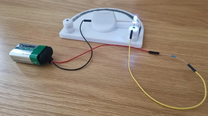
What you’re looking at here is a very simple potentiometer that bares its function for all to see. It consists of a 3D printed base and knob, which form the mechanical part of the device. A paper track is then laid on top to act as the main resistive element, once properly covered with graphite from a regular old pencil. From there, it’s as simple as adding the necessary contacts and wiper to the device, and you’ve got a potentiometer sitting in front of you.
What’s great about this build is that it’s very intuitive. Just by looking at it or putting it together, you get a straightforward understanding of everything that’s going on. By drawing the resistive trace, and by turning the knob, particularly if hooked up to an LED or something like in the demonstration, it’s easy to see how the potentiometer varies its resistance and affects a circuit.
We’ve featured some other fantastic teaching tools in the past, too. If you’ve got your own educational gems, be sure to let us know.


This would be great! If Step 1 weren’t “Buy a 3d printer.”
Use any shape you prefer. You can use a straight line on paper. “graphite from a regular old pencil” is apply-able anywhere.
Exactly! I remember learning about potentiometers and resistance with a demo that was nothing more than a line drawn on paper, a lightbulb* taped to a battery, and two leads to complete the circuit at whatever point you wished.
Not to disparage this project, which makes the whole thing more elegant, but it’s absolutely not necessary for the basic demo.
back in my day, we didn’t have LEDs, *or 3D printers, and we had to walk to school in deep snow uphill both ways, etc, etc.
hmm, and I see there is a problem with using asterisks** for footnotes when they’re also used for italics.
This is the method I use to explain resistance when teaching electronics to youth. They have more fun than expected experimenting with thin/wide, light/heavy, short/long lines. My favorite is when they inevitably wonder what happens if a circle is drawn instead of a line, and then a square… Great question, try it!
I do like DiscoLapy’s design, and will definitely build one. It looks like a great way to easily visualize how the internals of a pot actually work. It’ll be a good addition to the graphite line demonstration. Multiple interactive examples demonstrating the same thing, done in slightly different ways, is always helpful.
Sharpen a pencil, split it open lengthways and use some alligator clips etc to make a linear potentiometer.
Why sharpen it then?
So you have something for the alligator clip to hold on to at the end.
Though technically if it’s only on one end, it’s called a rheostat instead of a potentiometer.
Sounds dangerous done with a knife. Just buy some mechanical pencil “leads”, glue to a flat hard substrate so it won’t break. Harder types (H) may have less clay filler and different resistance.
A carpenter’s pencil is very suitable for this.
You don’t need a 3d printed flat plate. Use anything small and flat. Wood, plastic, anything to hand.
Years back, I made a potentiometer with carbon powder and acrylic paint for the binder.
How to make the paste, you take medicinal charcoal tablets and crush them to fine dust in a mortar, then mix it 50:50 in volume with acrylic paint from an arts supply store. Any color will do. Black probably already contains carbon, but some other color will let you see that you’ve mixed it properly.
Then, you take very thin plastic sheet, sand the edges straight and square, and glue two pieces on top of a third so you get a narrow trench between the edges. What I did, I made the trench wider at one end because I wanted a non-linear potentiometer.
Then you take the paste you just made with the paint, and stuff it in the trench, pressing it down with a spatula because it’s a little stiff and crumbly. Try to fill every tiny gap. Make it a tiny bit proud of the surface so when it dries it can shrink back, but try to leave it as close as possible because it’s hard and messy to sand down. Then when it’s dry, you come back with a sanding block and level it down to the plastic.
You can put copper or aluminum tape on the bottom of the trench if you wish, or you can put the contacts down on top later, with some clamping mechanism to maintain the contact in either case. You can make a potentiometer in the hundreds of Ohms up to couple tens of kilo-Ohms like this. If you do it with care, it’s much more durable and repeatable than scribbling a bunch of pencil lines on paper. The carbon powder is hard enough that you can put a brass wiper on it, and the brass will wear out faster.
Than u dude
Some 1990s “book of experiments for kids” had a similar thing with battery, pencil lead and a flashlight bulb.
If you use your imagination, such a potentiometer can be used to measure voltages to 0.1% with a 2% moving coil meter. That’s what we had to do at school.
The only extra component required is a known voltage; we used a Weston standard cell.
That’s what we had to do in physics at Purdue but that long resistor and ruler instead was a 10 turn pot. Took the fun part down a notch but a great introduction to the “super pot” that they are. 2 of them tune the oscillators on my Arp instead of the scratchy fine and coarse sliders originally used.