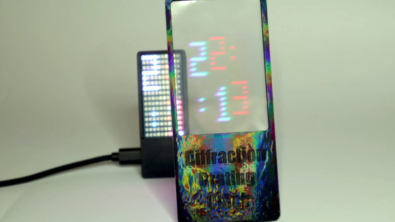
We’ve seen just about every possible way to make a clock here at Hackaday over the years. So it’s rare to have a first, but here we are with [Twisted & Tinned], who’s made a novel clock with a diffraction grating.
The display of the clock looks for all the world like a jumble of LEDs, that is, until you place the grating in front of it. Those LEDs are addressable multi-color parts, and each digit is generated at a different color all on top of each other. The grating splits out these colors, resulting in a magical set of floating LED figures.
Behind those LEDs is a Pi Pico, but that’s just one of many microcontrollers that could have powered this project. It’s the use of the diffraction grating in a novel way with those LEDs that makes the difference, and we rather like it. He’s also managed to get the grating pattern in the 3D printed surround for a shimmering look, by printing directly onto a diffraction grating sheet. That in particular is a technique we’ve looked at before in detail.


Funny and neat. :) But also economic! If the grating splits the basic 3 colors, you can have one line of 3 characters per 1 display with 1 character. That can save you 2 displays!
Probably someone already thought about this in the ’70’s or so. ;)
“Probably someone already thought about this in the ’70’s or so. ;)”
Oops, I forget there were only 2 colors of LED in the 70’s: red and green.
Could be, but they had color CRT’s and those RGB pixels are pretty close to each other too, so the concept as suggested is still viable I’d guess.
Now if we could easily buy those USHIO 8-in-1 LEDs
https://hackaday.io/project/2042-the-optical-inch/log/201306-ushio-epitex-to-deliver-8-led-clusters
Also, anyone remember what happened to polychromatic pixels that? Needs to explaining that this might be a fun match for the display hack above.
2021 https://opg.optica.org/ol/abstract.cfm?uri=ol-46-17-4358
2024 https://compoundsemiconductor.net/article/119170/Polychromatic_pixels
2025 https://www.semiconductor-today.com/news_items/2025/jul/qpixel-240725.shtml (hey at least it’s still online)
Their working principle: “A single-chip broad-spectrum multi-wavelength emission from 620 to 450 nm can be realized by changing the injection current to realize the regulation of carrier injection in the MQWs with different emission wavelengths.”
Something really went wrong with the undo and paste above. Apologies for the garbled mess.
“Also, anyone remember what happened to polychromatic pixels that shift wavelength based on drive current level? Needs no explaining that this might be a fun match for the display hack above.”
The figures can be previewed under https://www.researchgate.net/publication/353900486_Full-color_micro-LED_display_based_on_a_single_chip_with_two_types_of_InGaNGaN_MQWs/figures
Upon taking a second glance, the wavelength shifting only works up to an injection current level past which emission in the blue spectral range sets in.
RE: polychromatic pixels – I’ve read about them back then, too, thinking “volumetric/3D displays”.
Because diffraction lenses-wise that’s how holograms work.
My all your base clock (https://hackaday.io/project/1189-all-your-base-are-belong-to-us-clock) has an overlay mode that does red and green ontop of each other resulting in yello for shared segments. It’s not that hard to get used to reading overlaid digits. I have played around with doing a full RGB clock with hours/minutes/seconds overlaid ontop of each other and that is far too messy to parse in any reasonable time (7 different colors to deal with, 3 of which are relevant for a given digit type). A diffraction grating is an interesting way to split the colors appart again.