
In the cross-over between the era of tapes into that of MP3s, you’d see quite a few of those special cassette tapes that were actually digital music players inside. Some simply provided a 3.5 mm input, while others were complete MP3 players or Bluetooth receivers that just happened to also output to the magnetic read head of a cassette player. Recently [Jonathan Rowny] decided to make his own version of the latter.
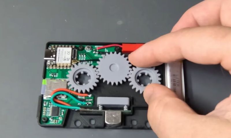
Although getting the actual audio signal into the read head is easy enough – requiring little more than its equivalent being used as a write head on the cassette side – actually interfacing with the player’s mechanisms like auto-stop, reverse and so on requires the use of some gearing that detect motion on what would be the tape spools, as well as transfer the motion from the take-up spool to the other spool so that features like the auto-stop mechanism don’t get triggered.
A lot of inspiration here can be found in e.g. the videos made by [Clint] of [Lazy Game Reviews] who looked at a number of examples – including their internals – over the years, with various levels of functionality. For this particular implementation an ESP32-S3 module is used for the brains, along with a microSD card reader for music and a PCM5102 I2S audio codec to create the analog audio signal.
The gears were printed using an SLA printer and seem to work all right. Unfortunately he didn’t realize the importance of the capstan as the mechanism that actually transports the tape, so its motion was not measured as is done in the better cassette adapters. This will likely be corrected in a future iteration, however.












But can it transfer BASIC programs into a TRS-80 via the cassette tape interface? That is the ultimate dog chasing it’s tail.
Jokes aside, It would be interesting to know how much more challenging it gets to push this concept in other tape-related directions.
What sort of DAC would you need to emulate a tape being written to well enough to recover the audio being ‘recorded’?
How much more bandwidth would we be talking to build a fake VHS cartridge that allows you to take your choice of video signal and have a VCR believe it is what on the tape(and how much extra trouble would helical scan be?)
If you were feeling bloody-minded; what sort of (likely relatively high speed) interface would you need to build an LTO-8 emulator?
On an audio tape, there are 2 tracks … that are quite easy to follow. Only the tape moves, and the read / write head just needs to stand at the right place.
A VHS tape requires read heads to be mounted on a spinning drum, which should be a challenge for a home maker I think …
On a LTO8 there are more than 6000 tracks on a 13 mm wide tape. A tape head can read 32 tracks at once.
When reading, the tape moves at ~5m/s (18km/h or 11 mph).
All these brings lots of challenges, and engineers work hard to write tape following algorithms to ensure the drive’s head follows the track accurately at 5 m/s …
Moreover, with such thin tracks, engineers have to deal with tape expansion due to temperature and humidity. With the tape expanding, the 32 tracks of the read head are not all lined up with the tracks on the tape which requires another system to line up the read head with the tracks on the tape.
By design, tape drives head are made to wore against tapes. The idea is that you can repair a tape drive (by changing it’s head with a new one), but you cannot easily rebuild the data on a damaged tape. So the more expensive thing is the tape drive, not the tape itself.
At last … I think it would be a non sense to emulate a tape drive with all these challenges, when it would be easier to build the correct interface (Fibre Chanel, SAS, iSCSI …). And think about the price of a tape, which is ridiculous compared to other data storage (HDD, SSD, …)…
This should not be too hard to implement in the firmware.
Also, it´s nice to see he managed to fit a battery in it.
What I haven’t see yet is a dual-head fake cassette that also supports recording. That´s a bit more difficult, but not impossible…
I don’t see why that wouldn’t be possible, although on this day and age it would be painstakingly slow.
It was slow in it’s day. I was in heaven when I got the 5 1/4″ floppy for my CoCo ;-)
the slow loading times of cassette on my zx spectrum was when i did my homework. if i had of gotten a disk drive i would have failed so many classes :-)
Unless you had a lcd handheld for the wait.
1200 baud on the coco.
Is ok. Programs are small. There are sandwiches to make. Kool aid to mix.
The programs were small but many systems used error-correction blocks or stored data blocks repeatedly after each other.
The number of blocks did depend on computer system as well as on the recording itself.
Commercial software tapes might contain a different number of those blocks than a tape that had been saved to on a home computer at home (different default values).
All because the MC/Compact Cassette was such an amateurish, unreliable medium.
In some ways it was worse than shortwave radio.
If the tape mechanics and the tape were cheap (-likely-) then there was wow, flutter and warble.
And both software and datasette hardware had to compensate for it.
The sad thing is that this wasn’t neccessary.
There were musical tapes that were of higher quality.
DAT tapes (1987), Type II, III and IV cassettes, D/CAS streamer tapes, special computer variants of MCs, microcassette etc.
But even the normal datasette drive would been more reliable if users would have been more sensible, more careful about the matter.
Because there were different cassettes of different quality, just like there was with HD and SD/DD floppy disks.
A normal music cassette from the super market around the corner wasn’t same as computer cassette (“Computape” and similar brands).
The tape material and the transport mechanism could differ greatly in quality.
But of course, most users either didn’t know or waved this away, thinking special tape must be a scam.
Just like they did with HD floppy disks.. sigh.
Here’s a YT video that explains tape quality well, I think: https://www.youtube.com/watch?v=DDwi6Z9HF9I
Depending on the computer you’re trying to load code into, it might be as simple as plugging your phone in via 3.5mm jack and playing the recorded ‘tape’. There’s even bespoke apps to do it for you.
(eg: https://github.com/semack/zx_tape_player)
…..and then you’re up at 3 am 3D printing music on wax cylinders after you wrote the music yourself but in binary.
Ideally the gears could turn a little magnetic generator to charge up the battery.
That’s what I assumed the gears were for when I saw the image too!
Well, a capacitor rather than a battery. But yeah.
Unfortunately a quick chat with an LLM makes me think that we would be under the power threshold that an ESP32 would like. Might get like 200 mW of electricity before the tape player started to struggle with the resistance, which is low for an ESP32.
Maybe if the battery starts sagging you could have some mechanism that sleeps the ESP32 and tells the tape deck to continue “playing” to get some more juice in the battery before it tries to start sending data again
Fast Forward / Rewind, for more efficient charging.
A purpose built bluetooth audio chipset can stream audio into high-impedance speakers at ~100 mW, so it’s doable, although maybe not with the ESP32.
That’s what I was just thinking too. That battery will cap the replay time on this device. Alternatively, just run a wire out like those old CD to Cassette adapters that hooked into the headphone socket of the CD player. I don’t mind a wire for power if it means I don’t have to pull the device out and charge it and NOT listen to music while charging.
I have an ancient device from the early 2000s it’s a casset tape that plugs into the audio jack of anything and played it through any casset player it was made by Sony if this new gadget gets made id get one
Wow!!! This will go so well for those car enthusiast’s that refuse to remove the old radio or don’t like how expensive these “retro looking” head units are!
The only missing from the radio in my 96 Jeep Cherokee is Bluetooth. Any music I listen to is streamed and I can’t say I own music in any format. After using 4 different wired cassette adapters that all introduced noise and interference from the tiniest jostle of the cord and anything powered by electricity, I finally bought a Bluetooth capable one. Immediately the battery proved to be the weak link and the noise from the gears turning was very audible without all the static covering it up. 2 of the 4 gears were removed, then a tiny wall built from pla was glued around the ones that are required with some non conductive grease in the cavity I made. Secondly, I hung a 850mah LiHV battery out the side of the adapter which gives me over 12 hours of play time. Lastly, as a bonus, the board had some unpopulated pads which were for a button to pick up/hang up or mute. So there’s a button and a battery hanging out of my tape deck but it works pretty awesome now.
My wife has a solution in her car — its a Bluetooth to FM adapter that also doubles as a USB power source that plugs into the cigarette lighter socket found on old cars. Music is streamed via Bluetooth to this adapter that then transmits it on the FM channel of your choice to the radio. (It will answer the phone etc. but we’ve never used it for that.)
Incidentally, my 1997 Jeep Grand Cherokee had a really unusual radio in it — it could receive AM stereo. AFAIK it was only ever used by one station, and then just for its jingle (and this ceased when it moved its studios). The Jeep went to my son-in-law who just swapped the radio for a modern one.
I can understand them. Some vintage radios are beauties.
Those with vfd display, for example.
The only replacement radios worth an exchange are CB radio+auto radio combos that fit in a DIN bay. :)
They’re useful in oldtimer cars and youngtimer cars (all vintage cars),
so the drivers can communicate with each others if they travel together.
The CB radios should still be able to to handle good old AM, though.
So an AM/FM/SSB model would be great.
27 MHz to medium wave (AM) converters did exist, too.
So users can listen to 11m band on the AM radio.
The reception of FM signals is also possible by using slope detection (slightly detuning the radio signal).
Anyway, just thinking out loud! Hope you don’t mind! 😅
I think personally I’d have gone with an optical switch, none of the wearing parts associated with a physical encoder and, in the potential case of a hall switch, it eliminates having a moving magnetic field near the read head.
I’m pretty sure I saw something similar a few years back as a retail product.
I wonder if the guts of a wireless earphone could be repurposed as a more or less drop in replacement for this that would fit in an off the shelf cassette tape adaptor without having to 3d print anything or manufacturer a custom pcb.
using a as5047 with a 3mm diameter at the distance seen here would definitely require mumetal shielding given the small size/mass it would only require 4-8mils thickness
11:56, I love the way he shorts the battery while cutting the leads :D
Yep, that was a nice one, almost missed it.
For those who wonder about the gear system in those cassette adapters, it is to make the tape player believe that there is actually tape moving. Some players detect non movement of the reels and stop playback. It depend on what cassette player you have whether you can get away with leaving these out, mostly auto reverse systems require such a setup but in those cases you most likely need a 4 track head too.
Can I buy one? It’ll be perfect in my Teac cassette deck and get those AV meters flying. KC
Nice hack, I thought about similar thing no less than 15 year ago : ] Glad someone brought it to fruition.
There was slightly better solution, no, not with the cassette adapters, that was afterthought, with some of the older cassette players that, too, were afterthought. The cassette players that were missing the receiver, they had plug-in module that would replace the cassette, however, they were simpler than that, there were pushpins that would connect the receiver module directly with the power amp stage.
Methinks pushpins are easy to add, and if I’d be designing the thing I’d go with the pushpins solution. One can probably add little bit of logic that would disengage the capstan motor, too, thus, prolonging AAs.
Still, nice build, quite well thought-through, and thank you for sharing!
A version using those pushpins to connect the cassette player internal amplifier would only work with a specific player. Big internal differences are common even in same model of a device made with parts from a different subcontractor. A pushpin in a slightly wrong place could cause a disastrous short circuit. Some cheap cassette player could have a single large circuit board with a line voltage transformer without shielded terminals. Poking there with pushpins would be a shocking hazard.
There were many different versions, for example, Unitech cassette radio modules only worked with the Unitech players specifically built for these, Toshiba cassette players had their players and radios, and GPX had theirs, and Unisef had theirs. None were interchangeable, and the location of the pogo-pins (better term) were usually different. Some pogo-pins were at the bottom of the module, some were in the lower half, etc. It varied.
As far as I could tell, none of the radio modules were uniform, all had their own proprietary solutions unique to one particular cassette player.
(spoiler – I own more than a dozen of these, all work, even today, Toshiba seem to be the most widespread one in the US).
There was another similar ware, pocket radios that would plug into speakers with amplifier. I think those were called something like “cangaroo radios”, and some were really fakes, ie, the speakers were driven by the radio’s power amp.
There was a third kind, a cassette player (this time with a built-in radio) that would plug into specifically designed speakers, and some were not bad quality comparably speaking. I own one made by Quasar, but it is actually a twin of, I think, Panasonic, since Quasar shared a lot of circuits with Panasonic. There are also rare kinds that were sold by JC Penney and there were Unisefs that were for the cassette players (made by Unisef – though GPX had exact twins as well), and the radio was actually in the speakers, not in the player, ie, no radio, the cassette player had the pogo pins.
As stated, there was no particular standard followed among the makers, each had its own versions designed for one particular model only, usually the location of the pogo pins would differ anyway, so those could not be interchangeable.
RE: “…A version using those pushpins to connect the cassette player internal amplifier would only work with a specific player…” and it did – the plugin modules I described, 1980s through 1990s, were specific to one brand/model. Pogo pins location, circuitry, all was unique, so those were not interchangeable (though, there were limited runs of independently-made modules for specific players, most no-name kinds probably made in Taiwan or South Korea and sold through likes of JC Penney).
I remember in the early days of mp3 players, there was a standalone mp3 player that was shaped like a Cassette with small buttons and an audio jack, so you could use It to play mp3 with a cassette player or connect headphones to the audio jack and use It as a portable mp3 player. It was pretty cool.
The surgical gloves are cringe.
I see now he’s only using them while using the resin printer. I take back my cringe remark. Apologies. Latex gloves in youtube electronics videos are basically a meme at this point.