
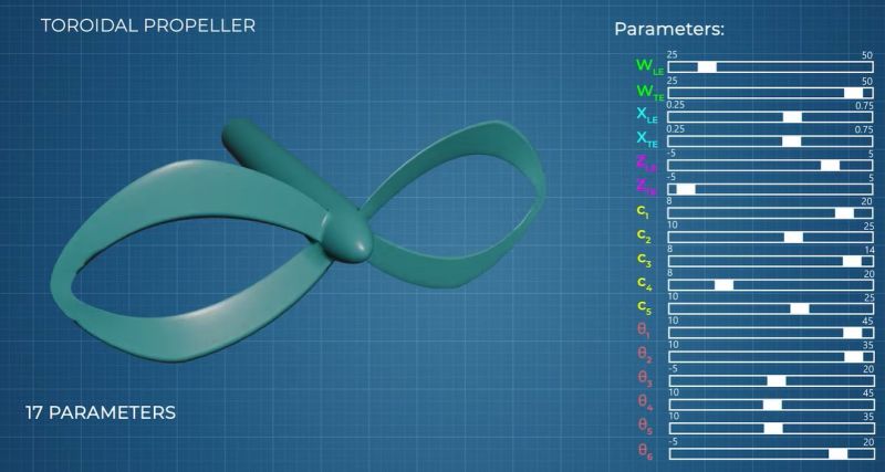
Although we often think that we got certain aspects of aerodynamics pretty much licked at this point, details like the optimal shape of a propeller remains hotly debated, both in- and outside of academia. This also includes wilder designs like toroidal propellers that even after more than a hundred years are still mostly just being evaluated. Recently [Neuronautics] took a shot at figuring out whether toroidal propellers even make sense.
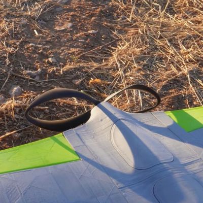
In order to do this, first an efficiency baseline was established using a conventional and highly optimized propeller. After scanning it in to get its exact geometry and running it through a computational fluid dynamics (CFD) simulation, the software spat out a number of about 73%.
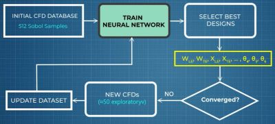
This left figuring out an optimized shape for the toroidal propeller to pit against it. While you can absolutely brute-force the seventeen shape parameters being considered here and test them in CFD, this would take insanely long. The hack here is to use multiple reference frame (MRF) to drastically speed up the selection process, though even then it still took two months. An example of using MRF with regular propellers is discussed in a 2019 paper by [Randi Franzke] et al. in Energies.
Although MRF saves a lot of simulation time, you still end up with a lot of data that has to be analyzed for interesting patterns. For this [Neuronautics] trained a artificial neural network to automate filtering the many options for the most optimal ones, until converging onto a single design.
This G1401 design was the lucky winner, though with only a simulated 62.9% efficiency. Subsequently the one aspect that had been left unchanged was also iterated through, in the form of many different airfoil shapes until the final design appeared.
This design was then 3D printed in resin, which showed the first hurdle with the selection process, in that the printed versions were too thin and flexible to be usable as propellers. Cue many hours of manual tweaking of the design to make it actually printable.
Although the final design didn’t exceed 62% efficiency in a final test, the comment section to the video rightfully points out that the comparison was between a commercially made propeller and a DIY resin-printed one, which adds a whole other batch of variables. That said, it’s unlikely that there’d have been an obvious improvement either way, otherwise we’d already have seen toroidal propellers pop up everywhere on drones and aircraft.











As usual, if a headline has a question mark in it, then the answer is always “no.”
AKA – Betteridge’s Law of Headlines.
https://en.wikipedia.org/wiki/Betteridge%27s_law_of_headlines
In the 80s, a comedy magazine had the headline “Is the Shah of Iran Really Dead? See p. 38”
Looked at page 38 to find the answer: “Yes”.
Maybe it was page 42 instead. Hitchhikers of the Universe knew that.
I appreciate that HAD didn’t title it such, or I would have skimmed it faster! Instead, it’s focused on the part we actually care about here: the experimentation and learning by making things ourselves.
Efficiency isn’t the only metric. It’d be nice to see more experiments towards (perceived) noise reduction.
Even injection moulded versions of this design are poor. Even if they were significantly more efficient, they’re extremely fragile compared to standard designs owing to the narrow band of material that fuses the rotor tips.
(I’ve tried them myself)
Different material perhaps?
People break the blades off stainless steel props on boats, with 5x the root thickness. The abuse a water based prop gets is unbelievable, you could make it out of almost anything and it would struggle to survive impacts.
I wonder if he tried to get FluidX3d running to improve on his CFD speed.
More turbulences, no?
That was my first thought, too, perhaps it does better job building laminar flow in the wake.
Were this to be scaled up for general aviation purposes for poops and pickles, I expect prop icing might become an interesting problem.
PhD about the propeller from 2018
https://research.chalmers.se/en/publication/505742
Is it my imagination, or does it look like four boomerangs joined together to form a pretzel?
A far as I remember the naive explanations, boomerang is partially a propeller, ie, one quadrant of the four-blade propeller, obviously, adjusted for different weight distribution (ie, more weight in the tips so that they balance out the middle; alssso, average boomerang HAS to be slightly offset, it cannot be completely symmetrical, since it has to do the cork-screw-fly trajectory, so sometimes one of the tips is slightly heavier than the other, and sometimes there are subtle differences between the blades).
Having said that, I think the present-day aircraft propellers designs had to do with the manufacturing, ie, reliable and consistent way of making usable blades, and I am quite sure it probably started with forged blade making, ie, forging, folding, forging, folding, ie, related to damascus blade making, which does not allow for any other shapes. 3D printing does, so do any reinforced kinds of materials, but I am also quite sure airplane making companies had looked into that already decades ago and found some kind of obstacles they could not overcome at the time.
Something like that.
Ie, three-pretzel-blade looks promising, and I wonder what the fluid mechanics for these would be. I suspect these would related to the multi-propeller kinds usually found on smaller-sized airplanes.
Correcting myself, multi-propeller kinds are found everywhere, reasoning for these is many, two propellers with smaller diameters is close to one propeller with the twice-as-large diameter, etc.
Metal airplane propeller blades are indeed forged, although the metal isn’t worked like a damascus knife or traditional sword during the process. Instead, a blank of steel or aluminum is die-forged into rough shape in a single step, then machined to final size (sometimes after having a twist added mechanically). There is, of course, a lot of very careful heat-treatment, tempering, etc, and the blanks can be much more complicated than a block of metal (modern blades are often hollow).
If I understood one of your points correctly, it takes 45 minutes to “evaluate” the CFD. Is that correct? If you can get an estimator down to a handful of minutes, you can use a genetic algorithm (GA) to fine tune the variables on your laptop/desktop machines. I have used GA’s for my previous work at NASA Goddard to calibrate various hydrological models. IIRC, that prior work also had ~16 to 20 variables, but also required high resolution 3D input (and as a result the objective function required 1 to 4 hours for each individual run). Instead of starting with a population of 500, you might be able to get it down to 50 to 100, but those choices involve a lot of testing, evaluation, and balancing the trade-offs. Also, since you already have months of modeling results, you might be able to datamine your previous results and feed them into a GA to see if several of the common search-space algorithms do any better. Also, one of the key points of a GA is that when a population comes close to converging on a solution, you can increase the “mutation rate” so that it can force it to explore different areas of the variable space. DM me if you want to give that a re-poke, and I can point you to a bunch of the tools I used at the time, and also tell you some tricks that help dial in your simulations, both your private equipment, and on cloud instances.
One other point that I do not think has been addressed is surface quality of your propeller vs. the commercial one you tested against. To give it a fair comparison, you should 3D print the conventional design you scanned, and see if the injection molded version is substantially different from a 3D printed one. This will test surface textures as well as flexing, and other properties.
Hope this helps.
Amazing work! Congrats. In one part of your CFD video it looks like a lot less swirl is left over in the propulsive wake. If you had a tractor prop airplane, instead of your pusher, would this effect smooth the wing’s airflow streamline? Think of GE’s RISE engine ….
Ah, but is it quieter? (That’s mostly what I care about)
Aaahhhh, de delight of reading the comments before watching a video about something so close to change our lifes, but not there yet. Like cold fusion. More popcorn please.
My understanding is that using the fewest blades possible ( 2 or more ) for a given required thrust and diameter is the most efficient. This design is equivalent to 6 blades.
Now take the principle and apply it to the impellers – the rotors and stators – of a jet turbine.
I wonder about adding golf ball dimples to the tips of a regular propeller, maybe getting the best of both worlds.
Perhaps adding piezoelectric elements to vibrate the propellers and make a low pressure cavity ahead of the leading edge.