Some kind of continuity beeper has been a standard piece of gear since the dawn of electronics. Sure, you probably have an ohm meter, but sometimes you don’t care about the actual resistance. You just want to know whether something connects or doesn’t, especially with a PCB trace or a cable. But what if your beeper could tell you more? [Nick Cornford] asks and answers that question with a beeper that lets you estimate resistance via pitch.
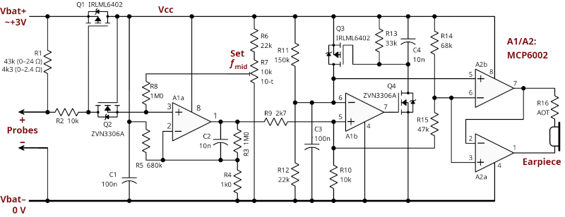
The circuit is relatively simple. A short to ground causes a voltage divider to produce a fraction of the battery voltage and a FET to conduct that fractional voltage to a VCO via a high-gain amplifier. The VCO converts voltage to frequency, and an audio amplifier feeds it to the speakers.
The two amplifiers and the VCO require two dual op-amp chips. The original schematic sends the output to some relatively high-impedance headphones. To drive more practical ones, the circuit can drop one op amp and use another FET and a separate battery.
Of course, you have many design choices, especially for the audio amplification. There are plenty of VCO circuits, or you could probably substitute a small microcontroller with an A/D converter and PWM output. Yes, you can also make a VCO with a 555.
VCOs are common because they are at the heart of PLLs.


There’s a somewhat fascinating continuity checker here> https://archive.org/details/EA1989/EA%201989-01%20January/page/n69/mode/1up
I feel it’d be a great automotive tool if it could also tell you if things are grounded or powered etc.
https://www.youtube.com/PowerProbeInc/videos
I still have a Beepo that is like 35 years old.
Cue hundreds of comments telling about the Testofon or Contitest or many other beepers that do this and more with only 3 transistors (two garden variety NPNs and a PNP)
Since resistance drives frequency, it should also be able to measure capacitance, leakage current, diodes and transistors.
This is one of the best measurement devices. If you’re fixing stuff, Ballpark is all you need and this instrument will tell that in incredibly short time and you don’t even have to take your eyes of the probes.
IMO the very best continuity tester is an old seatbelt buzzer from a vintage Detroit car. Add a 9V battery and two test leads-Done. Loud enough to troubleshoot at a distance and the current draw is helpful troubleshooting.
9005 or 9006 headlight bulb for high amp circuit integrity check, 3057 for medium stuff, 194 for low (relay coils & solenoids)…
“…you could probably substitute a small microcontroller …”
So the new “Can you make it with a 555?” or ‘Does it play D00M?” is “Can you make it with [e.g.] an Arduino?”? Or “Can you make it with [e.g.] an Arduino that plays D00M?”
I say “[e.g.]” because I’m increasingly using ESP32’s, but with the Arduino IDE because I’m lazy. Don’t take away my glider T-shirt please.
since i only use that continuity tester function for very low resistance connections, it would be nice if the tone was scaled in such a way that the entire range of resistances from 0 ohm to 0.1 ohm was spread across an octave or two of tones. that way i could have a sense of how long the trace i was measuring ran or whether a short was very close by. still, with my experience i know that most of the resistance detected across low-resistance measurements are between my probe(s) and whatever it is I have pressed it (them) against.
If I’m understanding correctly, you could get that by changing the value of R1. The schematic already lists 43k for measuring 0 to 24 ohms vs 4k3 for measuring 0 to 2.4 ohms; maybe you want R1 to be a 220 ohm resistor.
Disclosure: I am not an EE, and was commenting partly to express my thanks for a schematic I find far more helpful than most schematics.
Polar Instruments has been making the Tone Ohm 950 test fixture for years with this function as well as a plane short circuit test. Its saved countless hours finding shorted smt components on densely packed PCBs.