Tech In Plain Sight: Microwave Ovens

Our homes are full of technological marvels, and, as a Hackaday reader, we are betting you know the basic ideas behind a microwave oven even if you haven’t torn one apart for transformers and magnetrons. So we aren’t going to explain how the magnetron rotates water molecules to produce uniform dielectric heating. However, when we see our microwave, we think about two things: 1) this thing is one of the most dangerous things in our house and 2) what makes that little turntable flip a different direction every time you run the thing?

First, a Little History
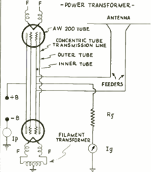
Westinghouse Powercaster which could, among other things, toast bread in six seconds

People think that Raytheon engineer Percy Spenser, the chief of their power tube division, noticed that while working with a magnetron he found his candy bar had melted. This is, apparently, true, but Spenser wasn’t the first to notice. He was, however, the first to investigate it and legend holds that he popped popcorn and blew up an egg on a colleague’s face (this sounds like an urban legend about “egg on your face” to us). The Raytheon patent goes back to 1945.

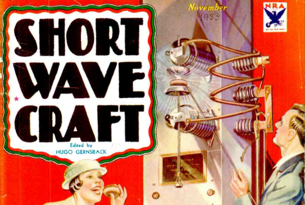
However, cooking with radio energy was not a new idea. In 1933, Westinghouse demonstrated cooking foods with a 10 kW 60 MHz transmitter (jump to page 394). According to reports, the device could toast bread in six seconds.  The same equipment could beam power and — reportedly — exposing yourself to the field caused “artificial fever” and an experience like having a cocktail, including a hangover on overindulgence. In fact, doctors would develop radiothermy to heat parts of the body locally, but we don’t suggest spending an hour in the device.

Continue reading “Tech In Plain Sight: Microwave Ovens”

New Electric Motor Tech Spins With No Magnets

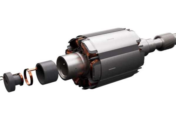
When you think of electric motors, you usually think of magnets. But magnets are heavy, and good magnets can pose problems when you need lots of them. A technology called SESM (separately excited synchronous motors) requires no magnets, but now ZF — a German company — claims to have a different scheme using inductive excitation. Motors that employ SESM tend to be larger and require a direct current to turn the rotor. This DC is often supplied by slip rings or an AC induction with a rectifier. The innovation here is that the inductive excitation is built completely into the shaft, which the company claims makes the motor both compact and powerful.

This kind of motor is usually destined for electric vehicles. The company claims the motor reduces losses by about 15% over conventional techniques. To maximize efficiency, conventional SESM uses slip rings or brushes to transmit power to the shaft. However, ZF claims their inductive improvements are even more efficient and can reduce axial size by around 90 mm.

Another advantage of the technology is that there is no need to provide a dry space for slip rings. That means fewer seals and the ability to cool the rotor with oil as you would with a motor containing permanent magnets. The company plans to offer a 400 V version of the motor and an 800 V that uses silicon carbide electronics.

If you build your own motors, have you tried anything like this? Usually, we don’t see motors this big, of course. We have, however, seen builds of reluctance motors that don’t use magnets.

Hacking A Christmas Tree For Less Blinkyness

Hacking a Christmas Tree to Blink Slower

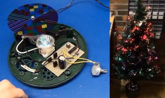
What good is a fiber optic self-lighting Christmas tree if it flashes so fast it will put you into an epileptic attack? The answer is “Not very good”, if you ask [Mads Nielsen] a.k.a [EcProjects]. So [EcProjects ] started a little project to slow the Christmas tree’s blinkyness down to a more reasonable rate. The task didn’t seem too difficult at first but turned into a quality tutorial building a variable frequency H-bridge motor control.

After opening the base of the tree [EcProjects] found a 12 volt AC geared synchronous motor turning a multi colored translucent plastic disk. A bright spotlight was shining upwards through the turning disk into the ends of hundreds of small fiber optics. This mechanism dumps loads of multi colored light out the ends of the fibers at the tips of the Christmas tree branches as the disk turns.

His goal was to slow down the motor; however, the rotation was based on the 50 Hz mains signal. In order to continue using this motor a lower frequency AC power source was needed. What follows in the video is an excellent lesson on how an AC synchronous motor works plus how to build a variable frequency control and H-bridge using some transistors, resistors and CMOS 4069 inverter chip.

In the end the frequency drive could only be lowered to about 30 Hz before the synchronous motor would stall and reverse using his design. [EcProjects] was bold enough to include several fails which always provides more opportunity for learning and is greatly appreciated.

If you believe you have a better solution please share your idea in the comments. I’m sure the first proposal will include an Arduino and servo modified for continuous rotation, but any solutions would be fascinating including modifications to his design. You can join us after the break to watch the video.

Continue reading “Hacking A Christmas Tree For Less Blinkyness”