Double The Resolution, From An Arduino ADC

Analog-to-digital converters, or ADCs, are somewhat monolithic devices for most users, a black box that you ask nicely for the value on its input, and receive a number in return. For most readers, they will be built into whatever microcontroller is their platform of choice, and their resolution will be immutable, set by whatever circuitry is included upon the die. There are a few tricks that can be employed to get a bit more from a stock ADC though, and [Neris] has taken a look at a couple of them.

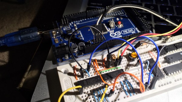
The first circuit doubles the resolution of an ADC, in this case, that of the Atmel chip in an Arduino, by converting its output from an integer to a signed integer. It performs this task with a precision rectifier, rectifying around a zero-crossing point half-way through the range of the analog value to be read and supplying a sign bit to the Arduino. The Arduino measures the rectified analog value to an integer, and applies the appropriate sign from the supplied bit value.

The second circuit takes a variation on the same technique but with two ADCs instead of one. A pair of PIC chips are used with their voltage references stacked one above the other, by taking both readings in combination a result with double the resolution can be derived.

You might ask why bother with these techniques. After all, there are plenty of higher-resolution ADCs on the market. But they’re useful techniques to know, should you ever need to extract the proverbial quart from a pint pot.

If ADCs are a mystery to you, you’re in luck. [Bil Herd] gave us a comprehensive introduction to the subject.

8-Channel ADC For The Raspberry Pi

The Raspberry Pi is a powerful embedded computing platform. However, for all its Linux-based muscle, it lacks one thing that even the simplest 8-bit microcontrollers usually have – analog-to-digital conversion. There are a great many ways to rectify this shortcoming, and [Chris Burgess] has brought us another – with an 8-channel ADC for the Raspberry Pi.

For the ADC, [Chris] chose the MCP3008, for its low cost and availability. In this configuration it offers 10-bit resolution and a maximum sampling rate of 200 kilosamples per second. Adafruit has a great guide on working with the MCP3008, too. With such a useful resource to hand, [Chris] was able to spin up a PCB to interface the chip to the Raspberry Pi using SPI. [Chris] took care to try to make the board to the official HAT specifications. As far as the physical aspects go, the board is to spec, however [Chris] omitted the EEPROM required for auto-configuration purposes. That said, the pads are on the board if someone wants to take the initiative to install one.

It’s a tidy build that provides something sorely missing from the Raspberry Pi, for a reasonable cost. [Chris]’s goal was to build something that would enable the measurement of analog sensors for a robot project; we’d love to hear your ideas for potential uses in the comments!

Playing With An Oscilloscope You’ll (probably) Never Own

We’ll have to admit that we were really jealous when [Shahriar] sent us a video he made, in which he casually explains how a $500,000 160GS/s 62GHz oscilloscope works and then starts playing with it.

Even though you need to be quite familiar with electronics to fully understand the oscilloscope’s inner workings, [Shahriar]’s step by step explanation is still approachable for those who only understand the basics.

In the first half of the video he uses the manufacturer’s documentation which contains the oscilloscope block diagrams, so you’ll also learn about:

  • timer interleaved Analog to Digital Converters (ADCs), which allows you to increase your input sampling rate by using several of them
  • phase-locked loops, which use a reference clock to generate a much faster clock signal
  • custom made dies and the materials used for high frequency electronic components

In the second half of the video [Shahriar] connects a pseudo random binary sequence generator and uses the oscilloscope to make several measurements that you’d typically want to know for high speed signals (jitters, eye quality factor…). He later performs a small experiment where he up-converts the frequency components of two random 3.12Gbit/s signals and tries to recall each original signal using the oscilloscope functions, making this part of the video a bit harder to keep up with.